Cable laying device and wind turbine
A cable and component technology, applied in the field of auxiliary equipment for wind turbines, can solve problems such as easy wiring damage, achieve good protection, and solve the effect of easy damage and breakage
- Summary
- Abstract
- Description
- Claims
- Application Information
AI Technical Summary
Problems solved by technology
Method used
Image
Examples
Embodiment 1
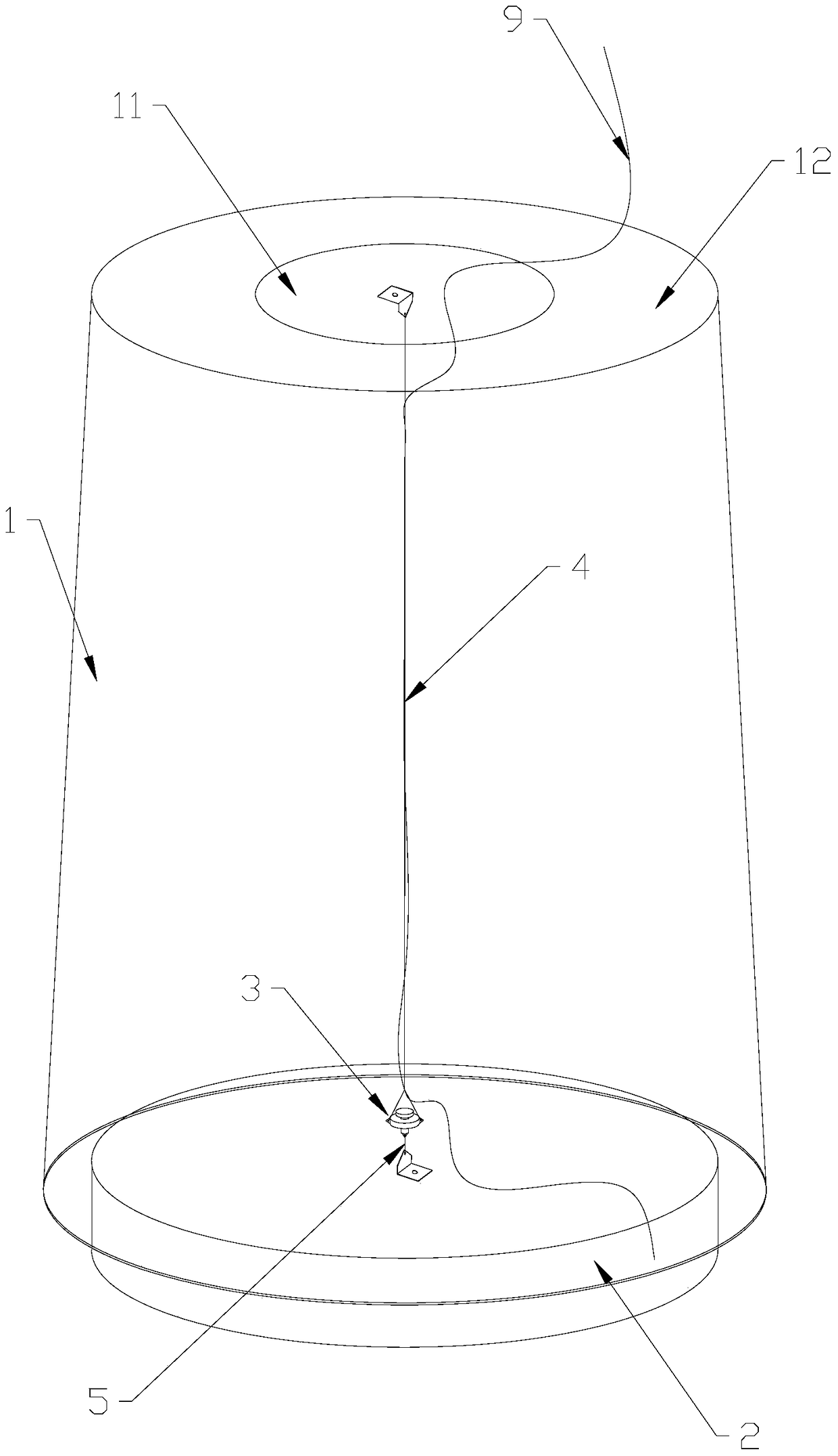
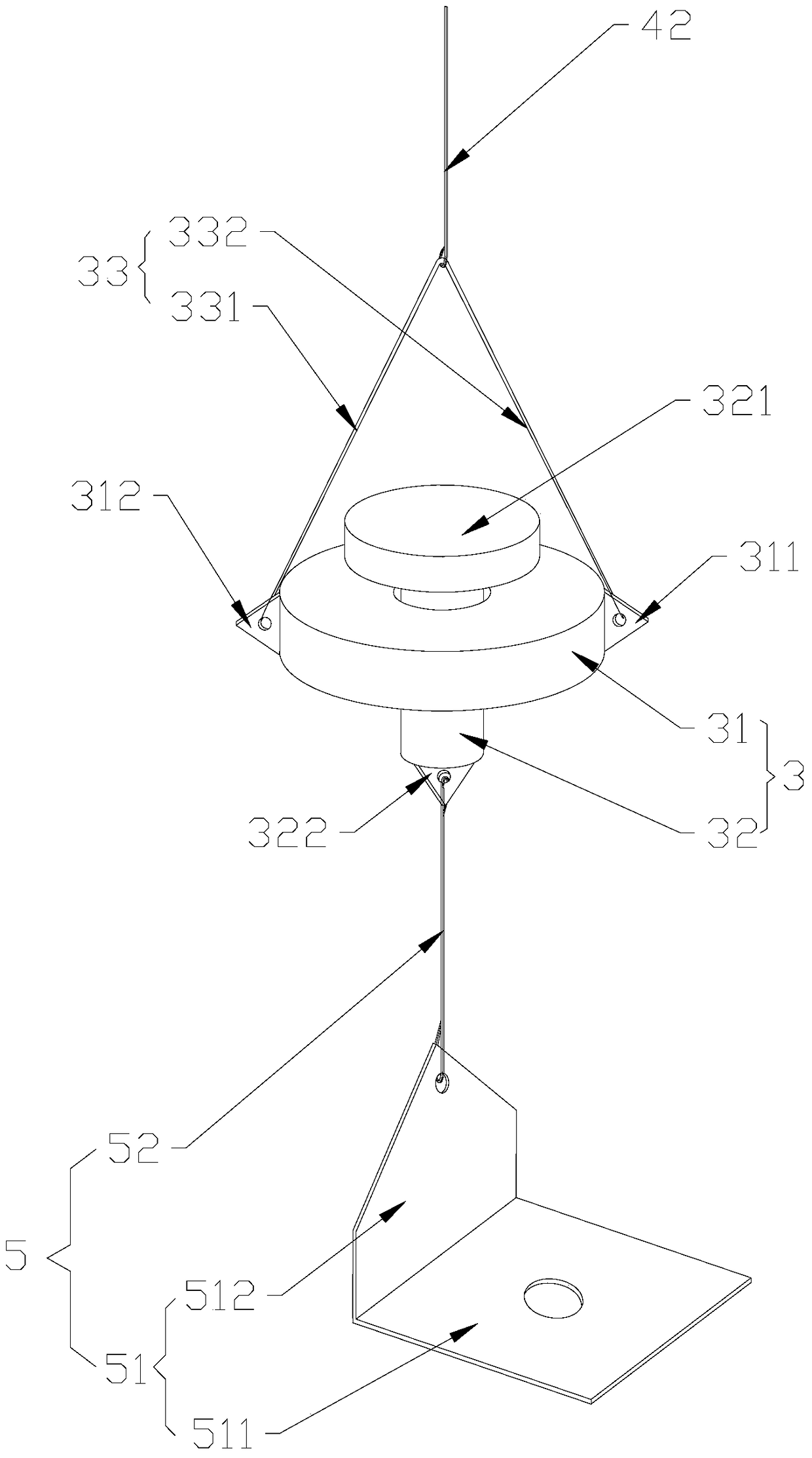
[0028] Such as figure 1 and figure 2 As shown, according to the embodiment of the present invention, the cable laying device includes: a rotating shaft assembly 3 , a first connecting part 4 and a second connecting part 5 . The rotating shaft assembly 3 includes an outer rotating shaft 31 and an inner rotating shaft 32 passing through and limited in the outer rotating shaft 31 , the inner rotating shaft 32 can rotate relative to the outer rotating shaft 31 . The first end of the first connecting member 4 is connected to the outer rotating shaft 31 , and the second end of the first connecting member 4 is fixedly connected to the first mounting object. The first end of the second connecting member 5 is connected to the inner rotating shaft 32, the second end of the second connecting member 5 is fixedly connected to the second mounting object, and the first mounting object is rotatable relative to the second mounting object.
[0029] When the first mounting object rotates rela...
Embodiment 2
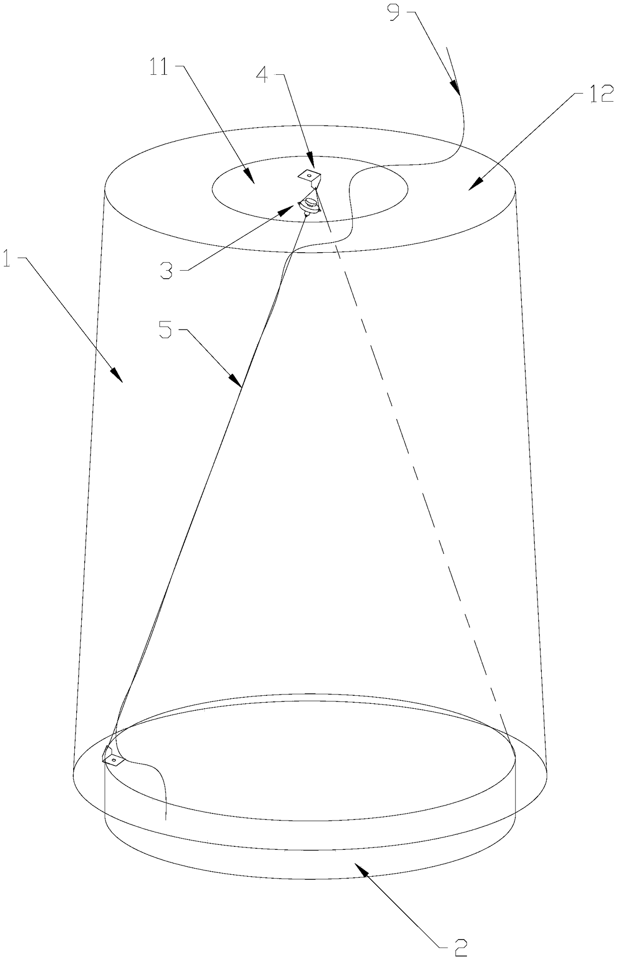
[0055] Such as image 3 and Figure 4 As shown, due to the difference in the structure of the blade 1 or the structure of the hub 2, it may not be possible to select the center point as the fixed point. In this embodiment, except that the installation position of the fixing frame is different from that in the first embodiment, other things are the same as the first embodiment. Specifically, in this embodiment, the axis of the inner rotating shaft 32 has a first angle with the rotation axis of the first mounting object, and one of the second end of the first connecting member 4 and the second end of the second connecting member 5 Located on the rotation axis of the first mounting object.
[0056] In this embodiment, the first fixing frame 41 is fixed on the center of the blade 1, that is, it is on the rotation axis of the blade 1, and the second fixing frame 51 is not on the center of the hub 2, that is, it is not on the blade 1 on the axis of rotation. In order to ensure t...
Embodiment 3
[0060] Such as Figure 5 and Figure 6 As shown, in this embodiment, except that the two fixed points are not at the center of the circle, everything else is the same as in Embodiment 1. Specifically, the axis of the inner rotating shaft 32 coincides with the rotation axis of the first installation, there are at least two first connectors 4, at least two second connectors 5, and the second end of each first connector 4 and each The second end of the second connector 5 is not on the axis of rotation of the first installation, the first end of each first connector 4 is connected to the outer shaft 31, and the first end of each second connector 5 is connected to on the inner rotating shaft 32 and are all located on the axis of the inner rotating shaft 32 .
[0061] Since the fixed point of the first connecting piece 4 and the fixing point of the second connecting piece 5 are not on the rotation axis of the first installation, two first connecting pieces 4 and two second connect...
PUM
 Abstract
Description
Claims
Application Information
 - R&D
- Intellectual Property
- Life Sciences
- Materials
- Tech Scout
- Unparalleled Data Quality
- Higher Quality Content
- 60% Fewer Hallucinations
Browse by: Latest US Patents, China's latest patents, Technical Efficacy Thesaurus, Application Domain, Technology Topic, Popular Technical Reports.
© 2025 PatSnap. All rights reserved.Legal|Privacy policy|Modern Slavery Act Transparency Statement|Sitemap|About US| Contact US: help@patsnap.com


