Wire cable laying device and wind generating set

A cable and component technology, applied in the field of auxiliary equipment for wind turbines, can solve problems such as easy wiring damage, achieve good protection, and solve the effect of easy damage and breakage

Active Publication Date: 2016-04-20
BEIJING GOLDWIND SCI & CREATION WINDPOWER EQUIP
View PDF9 Cites 2 Cited by
  • Summary
  • Abstract
  • Description
  • Claims
  • Application Information

AI Technical Summary

Problems solved by technology

[0006] Embodiments of the present invention provide a cable laying device and a wind power generating set to solve the problem that the wiring inside the blades is easily damaged due to the pitch of the blades

Method used


Image

  • Wire cable laying device and wind generating set
  • Wire cable laying device and wind generating set
  • Wire cable laying device and wind generating set

Examples


Embodiment 1

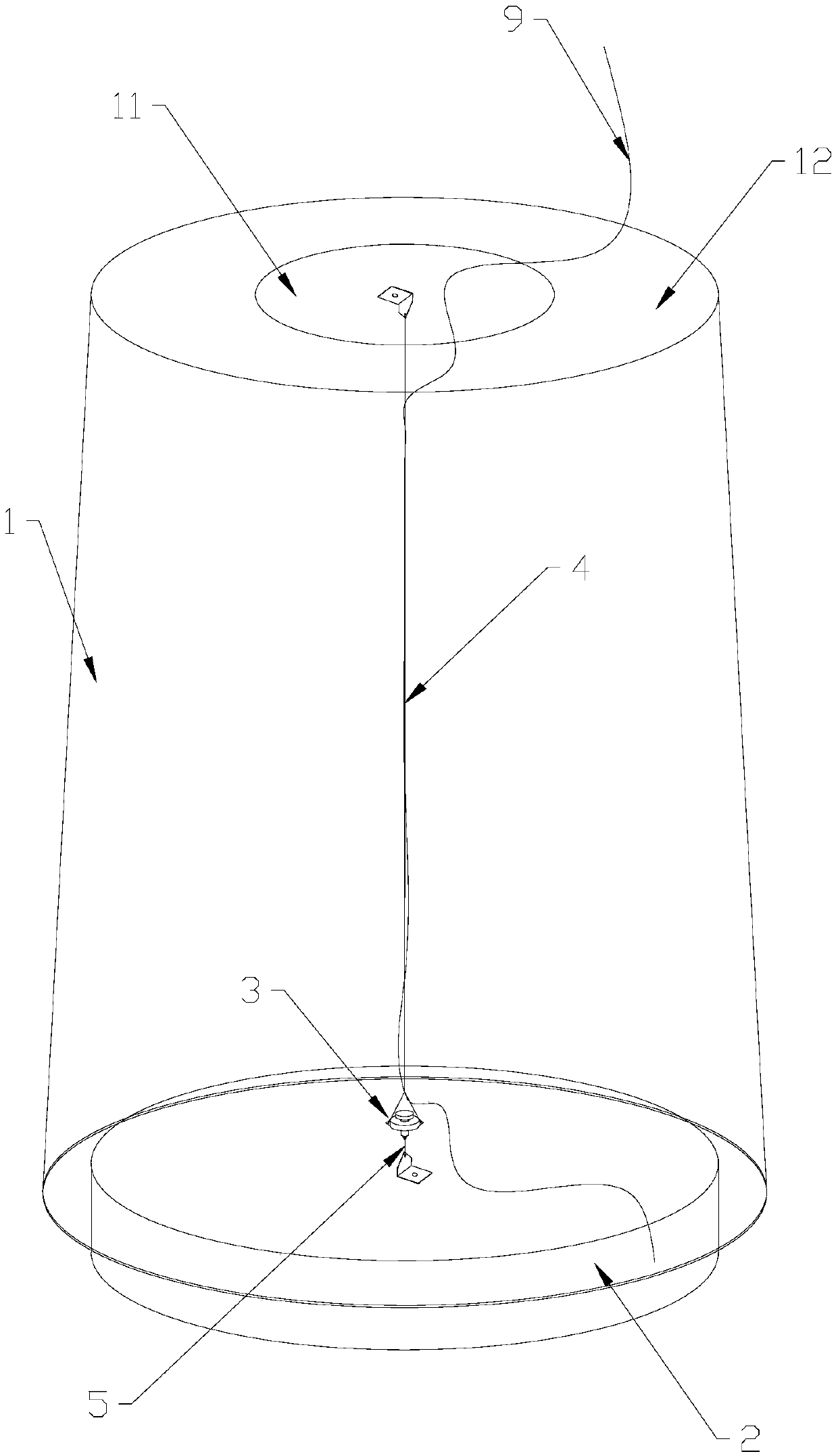
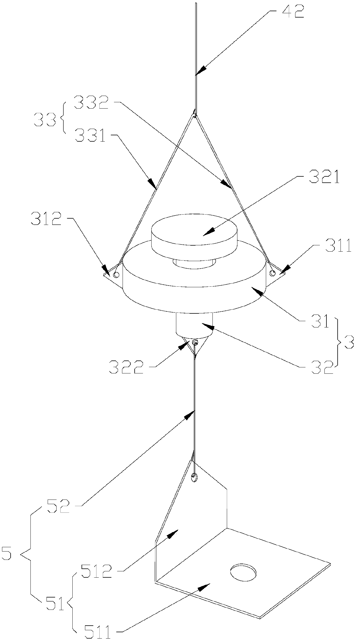
[0028] Such as figure 1 with figure 2 As shown, according to the embodiment of the present invention, the cable laying device includes: a rotating shaft assembly 3 , a first connecting part 4 and a second connecting part 5 . The rotating shaft assembly 3 includes an outer rotating shaft 31 and an inner rotating shaft 32 passing through and limited in the outer rotating shaft 31 , the inner rotating shaft 32 can rotate relative to the outer rotating shaft 31 . The first end of the first connecting member 4 is connected to the outer rotating shaft 31 , and the second end of the first connecting member 4 is fixedly connected to the first mounting object. The first end of the second connecting member 5 is connected to the inner rotating shaft 32, the second end of the second connecting member 5 is fixedly connected to the second mounting object, and the first mounting object is rotatable relative to the second mounting object.

[0029] When the first mounting object rotates rel...

Embodiment 2

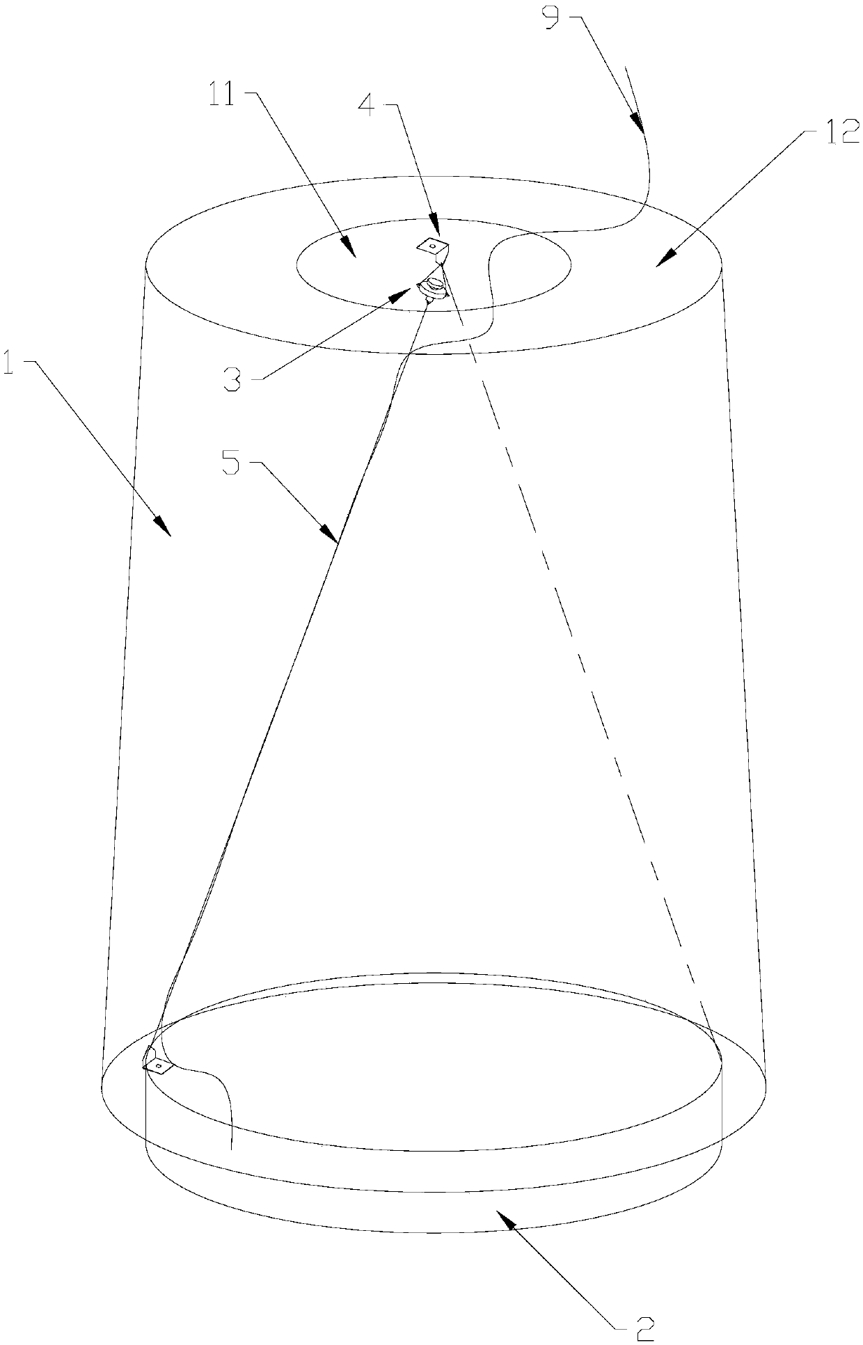
[0055] Such as image 3 with Figure 4 As shown, due to the difference in the structure of the blade 1 or the structure of the hub 2, it may not be possible to select the center point as the fixed point. In this embodiment, except that the installation position of the fixing frame is different from that in the first embodiment, other things are the same as the first embodiment. Specifically, in this embodiment, the axis of the inner rotating shaft 32 has a first angle with the rotation axis of the first mounting object, and one of the second end of the first connecting member 4 and the second end of the second connecting member 5 Located on the rotation axis of the first mounting object.

[0056] In this embodiment, the first fixing frame 41 is fixed on the center of the blade 1, that is, it is on the rotation axis of the blade 1, and the second fixing frame 51 is not on the center of the hub 2, that is, it is not on the blade 1 on the axis of rotation. In order to ensure ...

Embodiment 3

[0060] Such as Figure 5 with Image 6 As shown, in this embodiment, except that the two fixed points are not at the center of the circle, everything else is the same as in Embodiment 1. Specifically, the axis of the inner rotating shaft 32 coincides with the rotation axis of the first installation, there are at least two first connectors 4, at least two second connectors 5, and the second end of each first connector 4 and each The second end of the second connector 5 is not on the axis of rotation of the first installation, the first end of each first connector 4 is connected to the outer shaft 31, and the first end of each second connector 5 is connected to on the inner rotating shaft 32 and are all located on the axis of the inner rotating shaft 32 .

[0061]Since the fixed point of the first connecting piece 4 and the fixing point of the second connecting piece 5 are not on the rotation axis of the first installation, two first connecting pieces 4 and two second connecti...


PUM


Abstract

The invention provides a wire cable laying device and a wind generating set. The wire cable laying device comprises a rotary shaft assembly, a first connecting member and a second connecting member, wherein the rotary shaft assembly comprises an outer rotating shaft and an inner rotating shaft which penetrates into and is limited in the outer rotating shaft, and the inner rotating shaft can rotate relative to the outer rotating shaft; a first end of the first connecting member is connected with the outer rotating shaft, and a second end of the first connecting member is fixedly connected with a first mounted object; a first end of the second connecting member is connected with the inner rotating shaft, a second end of the second connecting member is fixedly connected with a second mounted object, and the first mounted object can rotate relative to the second mounted object. The wire cable laying device can guarantee no change in the length direction and can bear a centrifugal force of torsion and impeller rotation by using the rotary shaft assembly, so that the service life of a wire cable is guaranteed.

Description

technical field [0001] The invention relates to the field of auxiliary equipment for wind power generators, in particular to a cable laying device and a wind power generator. Background technique [0002] In wind turbines, more and more electrical systems are installed on the blades, including lightning online monitoring systems, blade deicing systems, vibration monitoring systems, fatigue detection systems, bearing lightning protection systems, etc. A common feature of these systems is that cables such as power lines, communication lines, and lightning protection down conductors need to be routed across the pitch bearing, and the blades and hubs at the pitch bearing rotate from 0° to 90°, so they are laid here The cables will be pulled and deformed when the blades are pitched, and due to the centrifugal force during the rotation of the impeller, the cables are more likely to be worn or broken. [0003] In the existing cable laying method, the patent CN101922407A uses elast...

Claims


Application Information

Patent Timeline
IPC IPC(8): F03D80/80
CPCY02E10/72
Inventor 李锐黄金鹏李强
Owner BEIJING GOLDWIND SCI & CREATION WINDPOWER EQUIP
Why Eureka
Try Eureka