
Electromagnetic brake capable of being controlled by rotating speed

A technology of electromagnetic brake and speed control, which is applied to automatic clutches, brake actuators, clutches, etc., and can solve problems such as inability to realize clutches

Inactive Publication Date: 2016-04-20
TIANJIN LINGJIE TRANS TECH
View PDF7 Cites 1 Cited by
  • Summary
  • Abstract
  • Description
  • Claims
  • Application Information

AI Technical Summary

Problems solved by technology

Existing electromagnetic clutch brakes often only rely on power on and off to control the transmission of torque. Once the power is off, the clutch function cannot be realized.

Method used


Image

  • Electromagnetic brake capable of being controlled by rotating speed

Examples


Embodiment Construction

[0013] It should be noted that, in the case of no conflict, the embodiments of the present invention and the features in the embodiments can be combined with each other.

[0014] In describing the present invention, it should be understood that the terms "center", "longitudinal", "transverse", "upper", "lower", "front", "rear", "left", "right", " The orientations or positional relationships indicated by "vertical", "horizontal", "top", "bottom", "inner" and "outer" are based on the orientations or positional relationships shown in the drawings, and are only for the convenience of describing the present invention and Simplified descriptions, rather than indicating or implying that the device or element referred to must have a particular orientation, be constructed and operate in a particular orientation, and thus should not be construed as limiting the invention.

[0015] In the description of the present invention, it should be noted that unless otherwise specified and limited...


PUM


Abstract

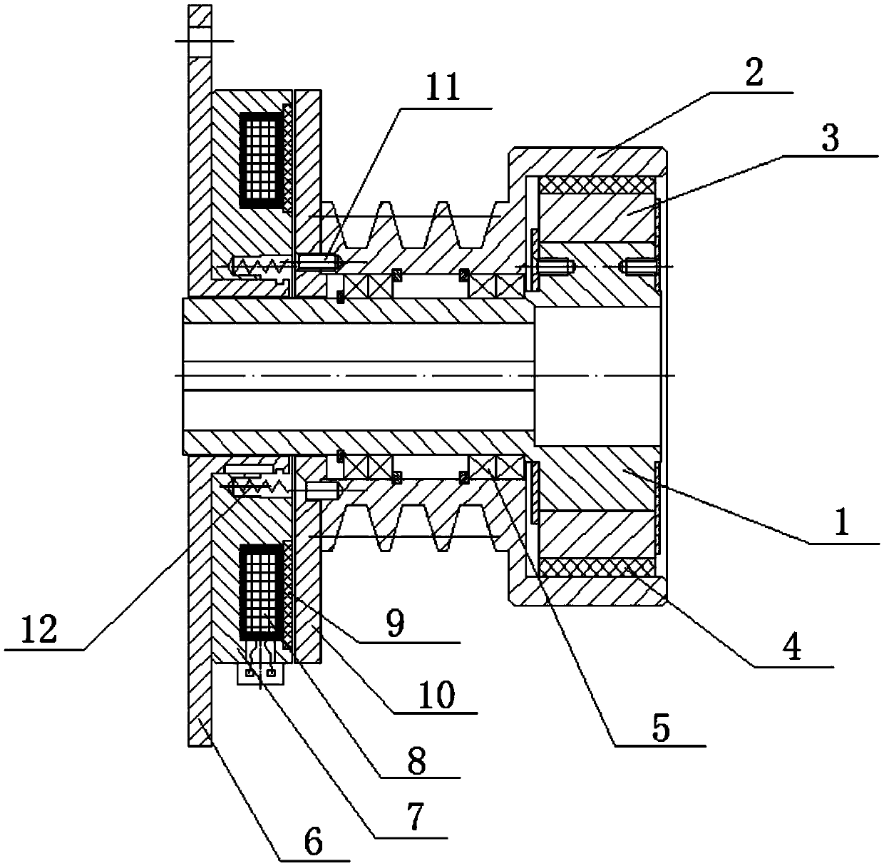
The invention provides an electromagnetic brake capable of being controlled by a rotating speed. The electromagnetic brake comprises an axle sleeve, a belt pulley, a flail block and a clutch friction plate. The belt pulley is rotationally connected to the axle sleeve by a bearing; the flail block is clamped outside the axle sleeve by a stretched spring; the clutch friction plate is adhered and connected to the outside of the flail block; a brake gap is reserved between the clutch friction plate and the belt pulley. The electromagnetic brake has the beneficial effects that transmission of a torque can be controlled simultaneously by upper limit values of an electric signal and the rotating speed; the electromagnetic brake is strong in clutch control power, and is safe and reliable to use.

Description

technical field [0001] The invention belongs to the field of electromagnetic clutch and brake devices, in particular to an electromagnetic brake that can be controlled by rotating speed. Background technique [0002] The electromagnetic brake controls the engagement and disengagement of the clutch by turning on and off the power of the coil. Existing electromagnetic clutch brakes often only rely on power on and off to control the transmission of torque, once the power is cut off, the clutch function cannot be realized. Contents of the invention [0003] In view of this, the present invention aims to provide an electromagnetic brake that can be controlled by the rotational speed, and can control the transmission of the torque by the electric signal and the upper limit of the rotational speed at the same time. The control force of the clutch is strong, and the use is safe and reliable. [0004] In order to achieve the above object, technical solution of the present inventio...

Claims


Application Information

Patent Timeline
IPC IPC(8): F16D65/18F16D43/04F16D121/20
CPCF16D65/18F16D43/04F16D2121/20
Inventor 岳超
Owner TIANJIN LINGJIE TRANS TECH
Learn More