Inspecting device

A technology of inspection device and detection part, which is applied in the direction of electronic circuit testing, etc., can solve the problem of positional deviation of substrate and pressing part, and achieve the effect of suppressing positional deviation

Active Publication Date: 2016-04-20
FUJIFILM BUSINESS INNOVATION CORP
View PDF10 Cites 3 Cited by
  • Summary
  • Abstract
  • Description
  • Claims
  • Application Information

AI Technical Summary

Problems solved by technology

[0003] In an inspection device for inspecting a substrate, when the substrate is set on the moving part, since the moving part can move, when the pressing part presses the substrate to the moving part, the substrate and the pressing part may be misaligned. Happening

Method used


Image

  • Inspecting device
  • Inspecting device
  • Inspecting device

Examples


Embodiment Construction

[0030] Hereinafter, an example of embodiment of the present invention will be described based on the drawings.

[0031] (Structure of inspection device 10)

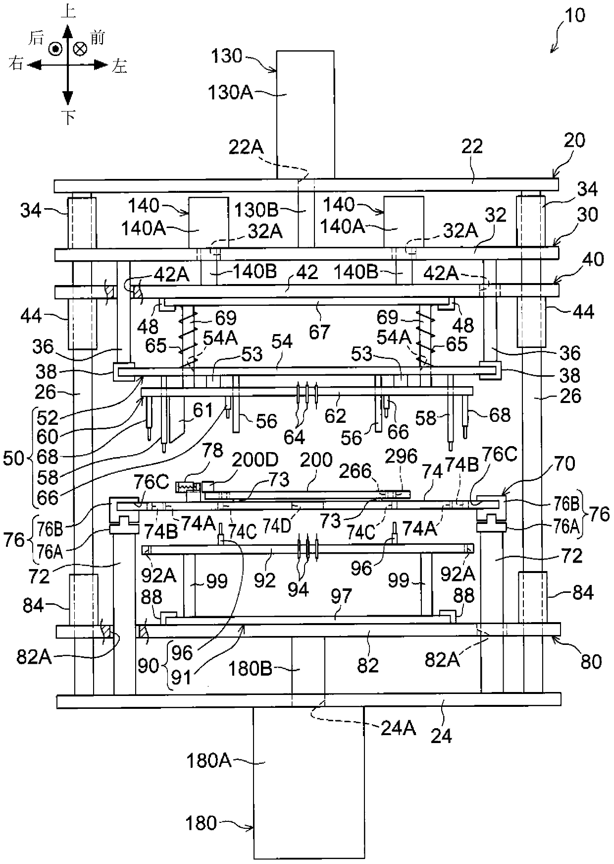
[0032] First, the configuration of the inspection device 10 will be described. figure 1 It is a rear view showing the structure of the inspection apparatus 10 of this embodiment. In addition, the front of the device, the rear of the device, the right of the device, the left of the device, the upper part of the device, the lower part of the device used in the following description, and the arrow directions (front, rear, right, left, up, down) shown in the drawings correspond. In addition, the symbols with "x" described in "○" in the figure represent arrows that go from the front to the back of the page. The symbols with "·" written in "○" in the figure represent arrows directed from the back side of the paper.

[0033] In the present embodiment, in the inspection apparatus 10, the side accessed by workers who perform t...


PUM


Abstract

The invention provides an inspecting device. The inspecting device is provided with a moving part, a pressing part, a positioning part, a declining part and a rising part. The moving part can move between an inspecting position for inspecting a substrate and a loading and unloading position for loading and unloading the substrate. The pressing part goes down from the upper side of the moving part which is on the inspecting position to a declining position, and presses the substrate to the moving part. When the pressing part presses the substrate to the moving part, the positioning part positions the moving part at least in the moving direction relative to the pressing part. When the moving part is on the inspecting position, the declining part goes down from the upper side of the inspecting position independently relative to the pressing part on the declining position. The declining part is provided with a first contact part, and the first contact part is electrically contacted with a first contacted part arranged on the upper surface of the substrate. When the moving part is on the inspecting position, the rising part rises from the lower side of the inspecting position independently relative to the pressing part on the declining position. The rising part is provided with a second contact part, and the second contact part is electrically contacted with a second contacted part arranged on the lower surface of the substrate.

Description

technical field [0001] The present invention relates to inspection devices. Background technique [0002] Japanese Patent Application Laid-Open No. 2000-199780 discloses such an inspection device: by lowering the upper unit and bringing the probe of the upper unit into contact with the upper surface of the printed substrate, at the same time, raising the lower unit so that the probe of the lower unit is in contact with the upper surface of the printed substrate. The bottom surface of the printed circuit board is contacted to inspect the printed circuit board. [0003] In an inspection device for inspecting a substrate, when the substrate is set on the moving part, since the moving part can move, when the pressing part presses the substrate to the moving part, the substrate and the pressing part may be misaligned. Condition. Contents of the invention [0004] It is an object of the present invention to suppress the pressing of the substrate by the pressing part to the mov...

Claims


Application Information

Patent Timeline
IPC IPC(8): G01R31/28
Inventor 中野雅广
Owner FUJIFILM BUSINESS INNOVATION CORP
Why Eureka
Try Eureka