A two-stage infrared thermal imager automatic gain control method

An automatic gain control, infrared thermal imager technology, applied in the field of infrared imaging, can solve the problems of reduced image expression, low gain coefficient k, insufficient contrast of output images, etc., to improve contrast, suppress bad element interference, and enhance image performance. force effect

Active Publication Date: 2018-06-08
TIANJIN JINHANG INST OF TECH PHYSICS
View PDF7 Cites 0 Cited by
  • Summary
  • Abstract
  • Description
  • Claims
  • Application Information

AI Technical Summary

Problems solved by technology

When there is bad element interference in the infrared image, the above-mentioned automatic gain control method will cause the calculated gain coefficient k to be low, so that the contrast of the output image is not enough
If the prior setting is used and the k value is increased, the saturated area in the image will increase and the image expressiveness will decrease.

Method used


Image

  • A two-stage infrared thermal imager automatic gain control method
  • A two-stage infrared thermal imager automatic gain control method
  • A two-stage infrared thermal imager automatic gain control method

Examples


Embodiment

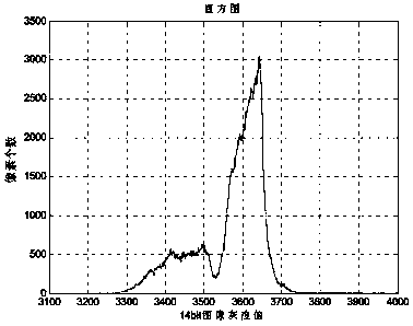
[0067] In this embodiment, a high dynamic (14 bit) range infrared image acquired by an uncooled infrared imager with a resolution of 640*512 is used to illustrate the application of the method of the present invention. The image contains n grey =656 effective gray levels, the total number of pixels N=640*512=327680, the maximum gray value p max =4904, the minimum gray value p min =3122, bad elements were processed before collection. The process that present embodiment uses processing method of the present invention is as follows:

[0068] Step 1: Calculate the histogram H of the input high dynamic range image; as figure 1 shown.

[0069] Step 2: According to the histogram H of the high dynamic range image, the formula (2) can be used to calculate N pe1 =1200, it can be calculated by applying formula (3), p e1 The maximum value is 3715, so that the total number of pixels with a gray value between 3715 and 4904 in the histogram H is greater than 1200, that is Similarly, ...


PUM


Abstract

The invention belongs to the technical field of infrared imaging, and in particular relates to a two-stage infrared thermal imager automatic gain control method. Compared with the prior art, the technical scheme of the present invention realizes the automatic control of the output gain of infrared images in different scenes. Compared with the traditional automatic gain control method, it is required to significantly improve the contrast of the output 8-bit image, suppress the interference of bad elements, and enhance the highlight area in the scene image expressiveness.

Description

technical field [0001] The invention belongs to the technical field of infrared imaging, and in particular relates to a two-stage infrared thermal imager automatic gain control method. Background technique [0002] In the process of infrared imager design, the original analog signal output by the infrared detector is usually sampled by 14-bit or 16-bit AD into a high dynamic range digital infrared image, while most display systems only accept image signal input in 8-bit data format, It is therefore necessary to convert the high dynamic range image data into an 8-bit image data format suitable for display. This process is called dynamic range transformation (also known as tone mapping - tone mapping). [0003] Among various dynamic range conversion high dynamic image display methods, the gain bias control method is one of the most commonly used image display methods, which has the advantages of adapting to a wide range of scenes, occupying less resources, and processing fast...

Claims


Application Information

Patent Timeline
Patent Type & Authority Patents(China)
IPC IPC(8): G06T5/40
CPCG06T5/40G06T2207/10048G06T2207/20208
Inventor 李科赵思宁马金鹏蔡小龙
Owner TIANJIN JINHANG INST OF TECH PHYSICS
Why Eureka
Try Eureka