Transformer

A transformer and conductive sheet technology, applied in the field of transformers, can solve the problems of large leakage inductance, poor coupling degree, poor efficiency, etc., and achieve the effect of increasing the coupling degree and reducing the voltage conversion efficiency

Inactive Publication Date: 2016-04-20
致茂电子(苏州)有限公司
View PDF5 Cites 0 Cited by
  • Summary
  • Abstract
  • Description
  • Claims
  • Application Information

AI Technical Summary

Problems solved by technology

Such a transformer will have a large gap between the first coil and the second coil, so that the degree of coupling between the two is not good, and a large leakage inductance will be generated
And when the leakage inductance is large, the voltage conversion efficiency of the first coil and the second coil is poor
Moreover, when the high-frequency switch is cut off, the surge voltage will be larger

Method used


Image

  • Transformer
  • Transformer
  • Transformer

Examples


Embodiment Construction

[0051] The detailed features and advantages of the present invention are described in detail below in the embodiments, the content of which is sufficient to enable anyone with ordinary knowledge in the art to understand the technical content of the present invention and implement it accordingly, and according to the content disclosed in this specification, the claims With the accompanying drawings, anyone with ordinary knowledge in the art can easily understand the related objects and advantages of the present invention. The following examples are to further describe the viewpoints of the present invention in detail, but not to limit the scope of the present invention in any way.

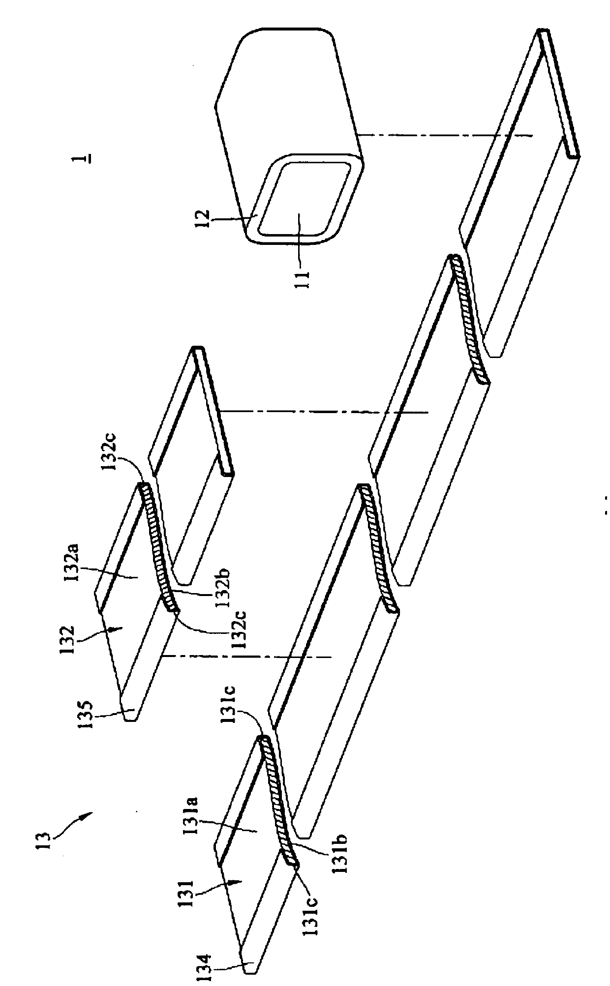
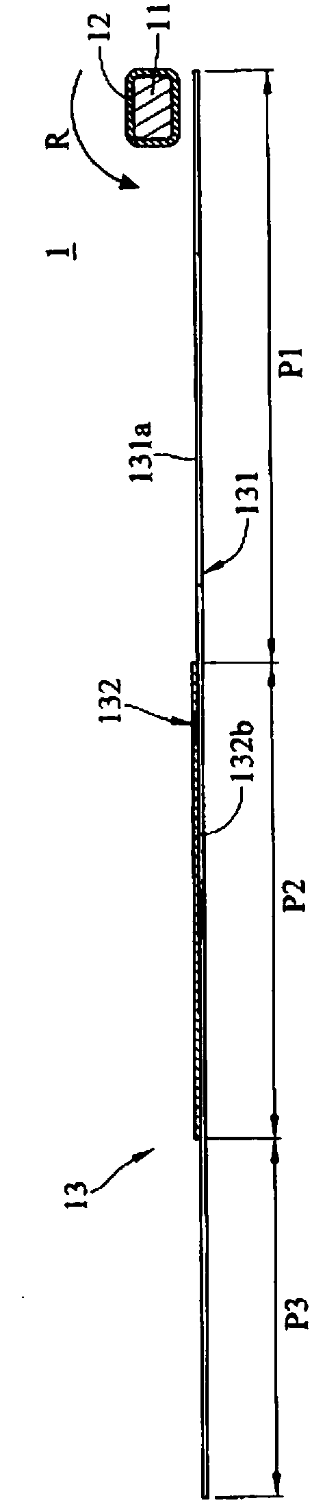
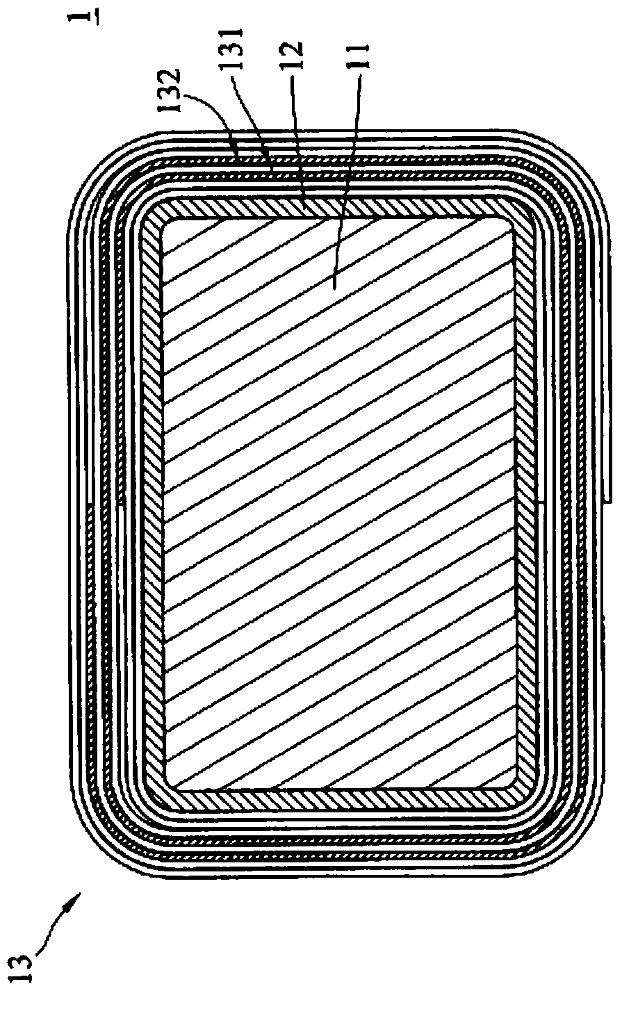
[0052] Please refer to figure 1 , figure 2 and image 3 , figure 1 is an exploded perspective view of a transformer 1 according to an embodiment of the present invention, figure 2 yes figure 1 An exploded schematic side view of the transformer 1, image 3 yes figure 1 Schematic side view of...


PUM


Abstract

The invention discloses a transformer which comprises a magnetic conductive core and an electric conductive part, wherein the electric conductive part comprises a first conducting plate and a second conducting plate which are mutually stacked and electrically insulated; the magnetic conductive core is wrapped by the electric conductive part; the magnetic conductive core is wrapped by the first conducting plate by over one circle; and the magnetic conductive core is wrapped by the second conducting plate for over one circle.

Description

technical field [0001] The invention relates to a transformer, in particular to a transformer with reduced leakage inductance. Background technique [0002] When electricity is used, various voltages are usually used to perform different tasks. For example, when a power plant intends to transmit electricity to a distant place after generating electricity, the voltage will be increased to tens of thousands of volts. When electricity is to be transmitted to the home, the voltage will be reduced to various voltage values ​​such as 220 volts, 110 volts or 100 volts according to the type of power usage and the laws and regulations of various countries. When the electronic device is to be used, the power must then be stepped down to various voltage levels. At this time, a transformer is often required for voltage conversion. [0003] The transformer generates magnetic force by inputting electric power to the first coil, and then guides the magnetic force to the second coil by t...

Claims


Application Information

Patent Timeline
Patent Type & Authority Applications(China)
IPC IPC(8): H01F27/28H01F27/32
Inventor 吴冠宏吴健铭简宏谚
Owner 致茂电子(苏州)有限公司
Why Eureka
Try Eureka