Method for protecting lens of camera head

A camera and lens technology, which is applied in the field of camera lens protection, can solve problems such as damage to parts, and achieve the effects of reducing installation costs, flexible applications, and a wide range of applications

Inactive Publication Date: 2016-04-20
CHENGDU BAIRUI BUILDING INSTALLATION ENG CO LTD
View PDF0 Cites 0 Cited by
  • Summary
  • Abstract
  • Description
  • Claims
  • Application Information

AI Technical Summary

Problems solved by technology

Based on the above advantages and uses, more and more cameras have entered people's life, study and production, but cameras are electronic products, and their parts are easily damaged by the outside world. Therefore, for different cameras, appropriate protection should be equipped. Grouped equipment

Method used


Image

  • Method for protecting lens of camera head
  • Method for protecting lens of camera head

Examples


Embodiment 1

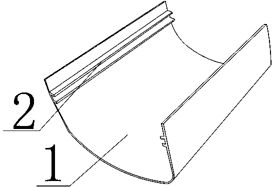
[0019] Such as figure 1 As shown, the present invention includes a protective cover body 1. The cross section of the protective cover body 1 is in the shape of "concave", and two mutually parallel convex strips 2 are arranged on the two inner sides of the "concave"-shaped protective cover body 1. Two convex lines 2 on the same side form a slide rail, and the two slide rails form a slide rail group.

Embodiment 2

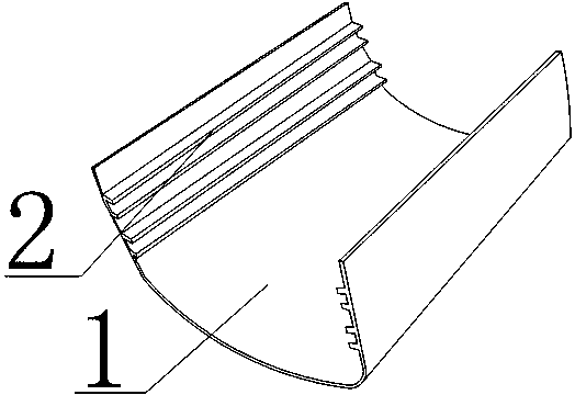
[0021] Such as figure 2 As shown, the present invention includes a protective cover body 1. The cross section of the protective cover body 1 is in the shape of "concave", and four mutually parallel convex strips 2 are arranged on the two inner sides of the "concave"-shaped protective cover body 1. Two adjacent protrusions 2 on the same side form a slide rail, and two slide rails at the same position on the two sides form a slide rail group, and there are two slide rail groups in total.


PUM


Abstract

The invention discloses a method for protecting lens of a camera head. A protection cover body (1) is provided. The whole cross section of the protection cover body (1) is of a recessed-type structure. Two side faces in the protection cover body (1) are at least provided with one sliding rail group. Each of the sliding rail groups comprises two independent sliding rails. The sliding rails are respectively arranged on two side faces of the protection cover body (1). Each of the sliding rails comprises two parallel protruding strips (2). According to the invention, via the connection between the sliding rail group and the groove in the camera head, the camera head can be installed in the protection cover body, thereby achieving an objective to protect the camera head; a relative position relation between the camera head and the protection cover body can be adjusted as required, so the camera head and the protection cover body can be flexibly applied; while installation cost of the camera head is reduced, numbers of the protection cover bodies are reduced, and shooting dead angles of camera heads at the same installation point are reduced, thereby facilitating monitoring; and requirements of different models of camera heads can be met, use range is wide and the structure is simple, convenient to use and practical.

Description

technical field [0001] The invention relates to a camera accessory, in particular to a method for protecting the camera lens. Background technique [0002] The working principle of the camera is roughly as follows: the optical image generated by the scene through the lens LENS is projected onto the surface of the image sensor, and then converted into an electrical signal, which is converted into a digital image signal after A / D conversion, and then sent to the digital signal processing chip DSP It is processed in the middle, and then transmitted to the computer for processing through the USB interface, and the image can be seen through the monitor. Cameras are divided into two categories: digital cameras and analog cameras: digital cameras can convert analog video signals generated by video capture devices into digital signals, and then store them in computers; video signals captured by analog cameras must be captured by specific video The card converts the analog signal in...

Claims


Application Information

Patent Timeline
Patent Type & Authority Applications(China)
IPC IPC(8): H04N5/225
Inventor 罗江
Owner CHENGDU BAIRUI BUILDING INSTALLATION ENG CO LTD
Why Eureka
Try Eureka