
Inserting rod of window cleaning machine

A technology of window cleaning machine and rod insertion, which is applied in the direction of window cleaning, cleaning equipment, household appliances, etc., can solve the problems of large diameter, expensive, and inability to use bearing costs of circular steel pipes, so as to improve convenience and reduce equipment weight. , the effect of reducing costs

Inactive Publication Date: 2016-04-27
BAIST EQUIP RENTAL SHANGHAI CO LTD
View PDF6 Cites 1 Cited by
  • Summary
  • Abstract
  • Description
  • Claims
  • Application Information

AI Technical Summary

Problems solved by technology

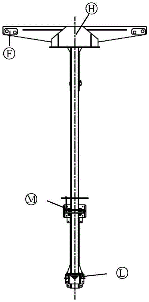
[0002] In the existing technology, such as figure 1 As shown, there are two types of slewing mechanism in the form of a plunger: one is that the cantilever and the pillar have relative motion, that is, the cantilever revolves around the pillar, a sliding bearing is installed at the H point, and more than 3 bearings are installed at the M point. The rotating roller in a loop is installed on the cantilever mechanism and also revolves around the pillar, that is, the roller is installed on the moving structure, the cantilever adopts a rectangular tube, and the pillar is used to allow the rotating roller connected to the cantilever to rotate around it. The other is that the cantilever and the pillar are integrated, that is, a large steel pipe is used, and a rolling bearing is installed at M, and a sliding bearing is installed at L. Loading force, the bending moment formed by it will be borne by the pillars, but we all know that the bending modulus of circular steel pipes is not good, and under the same bending moment, the size of circular steel pipes is much larger than that of rectangular pipes
Due to the very large diameter of the circular steel pipe, the bearings in the national standard cannot be used or the cost is very expensive

Method used


Image

  • Inserting rod of window cleaning machine
  • Inserting rod of window cleaning machine
  • Inserting rod of window cleaning machine

Examples


Embodiment Construction

[0022] The present invention will be described in detail below in conjunction with specific embodiments. The following examples will help those skilled in the art to further understand the present invention, but do not limit the present invention in any form. It should be noted that those skilled in the art can make several modifications and improvements without departing from the concept of the present invention. These all belong to the protection scope of the present invention.

[0023] figure 1 Shown is the form of the plunger in the prior art.

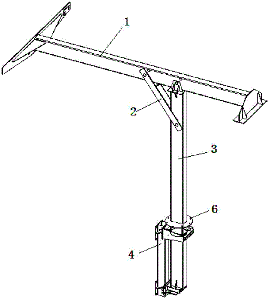
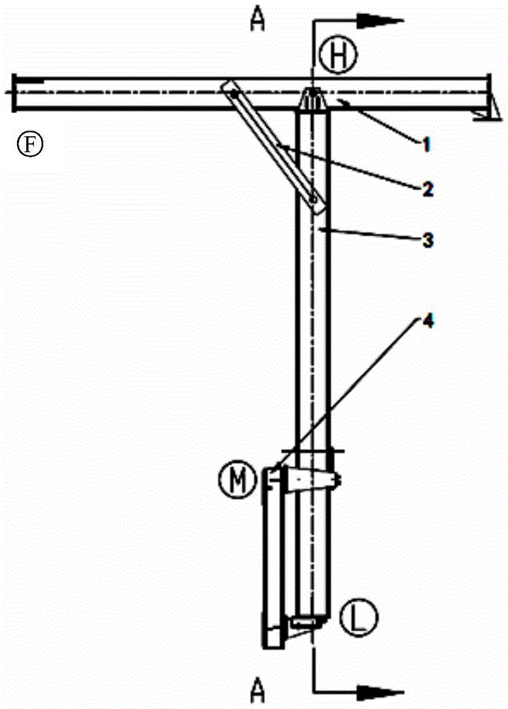
[0024] Figure 2-Figure 6 As shown, the insertion rod of the window cleaning machine provided by the present invention includes the upper part of the cantilever 1, the diagonal brace 2 and the pillar 3 to form a stable triangular structure. The cantilever 1 and the support 3 are formed into one body. A circle of four rotary rollers 5 is installed on the fixed frame 4 that partly arranges under the pillar. The fixed frame 4 in...


PUM


Abstract

The invention provides an inserting rod of a window cleaning machine. The inserting rod comprises a supporting pillar and a cantilever which is arranged at the upper end of the supporting pillar, and further comprises an inclined support, wherein a triangular structure is defined by the inclined support, the cantilever and the upper part of the supporting pillar; a fixed stand is arranged on the lower part of the supporting pillar; rotary rollers are arranged on the fixed stand; a rotary disc is welded on the peripheral side of the supporting pillar; the rotary rollers are used for supporting the rotary disc in the radial direction of the rotary disc; rolling bearings are arranged at the bottom of the supporting pillar for supporting the supporting pillar in a longitudinal direction; and both the cantilever and the supporting pillar are rectangular pipes. Since all rotary positions are in the form of the rolling bearings and since the cantilever and the supporting pillar are rectangular pipes, the operation convenience is greatly improved, and meanwhile equipment weight is greatly reduced and cost is reduced.

Description

technical field [0001] The invention relates to a window cleaning machine, in particular to an insertion rod of the window cleaning machine. Background technique [0002] In the prior art, such as figure 1 As shown, there are two types of slewing mechanism in the form of a plunger: one is that the cantilever and the pillar have relative motion, that is, the cantilever revolves around the pillar, a sliding bearing is installed at the H point, and more than 3 bearings are installed at the M point. The rotating roller in a loop is installed on the cantilever mechanism and also revolves around the pillar, that is, the roller is installed on the moving structure, the cantilever adopts a rectangular tube, and the pillar is used to allow the rotating roller connected to the cantilever to rotate around it. The other is that the cantilever and the pillar are integrated, that is, a large steel pipe is used, and a rolling bearing is installed at M, and a sliding bearing is installed a...

Claims


Application Information

Patent Timeline
IPC IPC(8): A47L1/00
Inventor 隋文科卓爱明
Owner BAIST EQUIP RENTAL SHANGHAI CO LTD
Learn More