Tyre clamping mechanism for vehicle production line

A technology of automobile production line and clamping mechanism, which is applied in the direction of motor vehicles, transportation and packaging, etc. It can solve the problems of increased difficulty in equipment maintenance, inability to popularize large-scale use, and increased frequency of equipment failure, achieving simple structure, safety and efficiency Precise positioning, the effect of preventing dead spots

Active Publication Date: 2016-04-27
武汉东研智慧设计研究院有限公司
View PDF4 Cites 4 Cited by
  • Summary
  • Abstract
  • Description
  • Claims
  • Application Information

AI Technical Summary

Problems solved by technology

[0002] In the automatic production line of automobiles, after the final assembly of the whole vehicle is completed on the production line, it is often necessary to perform many tests on the whole vehicle such as raining and four-wheel alignment. At this time, it is necessary to use a clamping mechanism to precisely position and clamp the vehicle , to prevent the phenomenon of running deviation and misalignment when the car is testing various parts. The traditional clamping mechanism generally clamps the chassis or body of the car. However, due to the large number of parts and complex structures of the car chassis, this The clamping mechanism can easily damage the underbody
In addition, the size of the car is too large, and the clamping mechanism is generally designed to be too bulky, which will easily lead to an increase in the frequency of equipment failures and increase the difficulty of equipment maintenance, making it impossible to popularize and use it on a large scale

Method used


Image

  • Tyre clamping mechanism for vehicle production line
  • Tyre clamping mechanism for vehicle production line
  • Tyre clamping mechanism for vehicle production line

Examples


Embodiment Construction

[0025] In order to make the object, technical solution and advantages of the present invention clearer, the present invention will be further described in detail below in conjunction with the accompanying drawings and embodiments. It should be understood that the specific embodiments described here are only used to explain the present invention, not to limit the present invention.

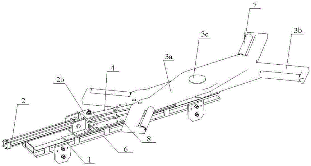
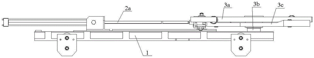
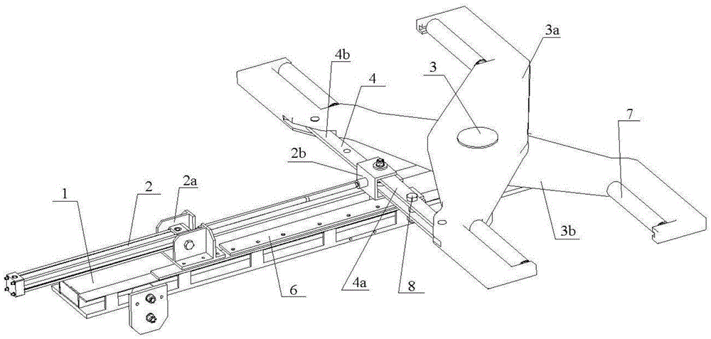
[0026] Such as Figure 1 to Figure 4 It can be seen from the structural schematic diagram of the tire clamping mechanism of the automobile production line shown that the tire clamping mechanism of the automobile production line of the present invention mainly includes a base 1; a driving device 2 is fixedly connected to the base 1; 2 and the holder 3 are connected through a push-pull rod 4; the driving device 2, the holder 3 and the push-pull rod 4 constitute a slider crank mechanism. Wherein the driving device 2 includes a horizontal thrust power source 2a and a push rod support 2b; the horizonta...


PUM


Abstract

The invention discloses a tyre clamping mechanism for a vehicle production line, and belongs to the field of vehicle assembling workshop mechanized transportation. The tyre clamping mechanism comprises a base, wherein a driving device is fixedly connected to the base; a clamp holder is also hinged to the base; the driving device and the clamp holder are connected through a push-pull rod; the driving device, the clamp holder and the push-pull rod form a slider-crank mechanism. The tyre clamping mechanism is characterized in that a guiding wheel which is horizontally arranged is arranged at the bottom end of a supporting seat of a push rod of the driving device; a guiding plate which can be cooperated with the guiding wheel is arranged on the base; the guiding wheel is tangent with the inner side wall of the guiding plate. According to the tyre clamping mechanism disclosed by the invention, the structure is simple, the clamp holder is driven by the driving device in the horizontal direction, so that a vehicle front wheel can be stably clamped, and the accurate clamping and positioning of a vehicle in a service position of an automatic production line is realized safely and efficiently.

Description

technical field [0001] The invention relates to an automobile clamping device, which belongs to the field of mechanized conveying in automobile assembly workshops, and in particular relates to a tire clamping mechanism used in an automobile automatic production line. Background technique [0002] In the automatic production line of automobiles, after the final assembly of the whole vehicle is completed on the production line, it is often necessary to perform many tests on the whole vehicle such as raining and four-wheel alignment. At this time, it is necessary to use a clamping mechanism to precisely position and clamp the vehicle , to prevent the phenomenon of running deviation and misalignment when the car is testing various parts. The traditional clamping mechanism generally clamps the chassis or body of the car. However, due to the large number of parts and complex structures of the car chassis, this The clamping mechanism can easily damage the underbody. In addition, t...

Claims


Application Information

Patent Timeline
Patent Type & Authority Applications(China)
IPC IPC(8): B62D65/12B62D65/18
CPCB62D65/12B62D65/18
Inventor 宋泰宇王银明胡全心董建国
Owner 武汉东研智慧设计研究院有限公司
Why Eureka
Try Eureka