A toilet flushing waterway structure and toilet seat with accelerated siphon

A waterway structure and waterway technology, applied in the field of sanitary ware, can solve the problems of slow air discharge, increased water consumption, unfavorable water conservation, etc., to achieve the effect of reducing flushing water consumption, increasing discharge speed, and facilitating early formation

Active Publication Date: 2018-02-13
XIAMEN R&T PLUMBING TECH
View PDF5 Cites 0 Cited by
  • Summary
  • Abstract
  • Description
  • Claims
  • Application Information

AI Technical Summary

Problems solved by technology

[0003] The flushing water circuit in the toilet seat is all full of air before each flushing work cycle. When the flushing starts, the amount of water entering the toilet water inlet 11 per unit time is far greater than the volume of air filled, and the water flow is almost at the rear end of the shared water circuit 10. Flow into the lap washing waterway 20 and the spray waterway 30 simultaneously, at this moment, the air in the spray waterway 30 is trapped between the shared waterway 10 and the water cover W (as figure 2 As shown), it may be partly discharged downward from the injection port 32 under the squeeze of flushing water, part of it is discharged from the toilet water inlet 11 against the water flow direction, and part of it enters the lap water circuit 20 and is discharged from the lap hole, while If more air in the spray waterway 30 is discharged from the spray port 32 or the toilet water inlet 11, it will greatly hinder the entire flushing process, greatly reduce the potential energy of the water, increase the water consumption, and the slow air discharge speed will cause The jet siphon is produced slowly, which is not conducive to saving water, and the overall flushing performance of the toilet is poor

Method used


Image

  • A toilet flushing waterway structure and toilet seat with accelerated siphon
  • A toilet flushing waterway structure and toilet seat with accelerated siphon
  • A toilet flushing waterway structure and toilet seat with accelerated siphon

Examples


Embodiment Construction

[0032] In order to make the technical problems, technical solutions and beneficial effects to be solved by the present invention clearer and clearer, the present invention will be further described in detail below in conjunction with the accompanying drawings and embodiments. It should be understood that the specific embodiments described here are only used to explain the present invention, not to limit the present invention.

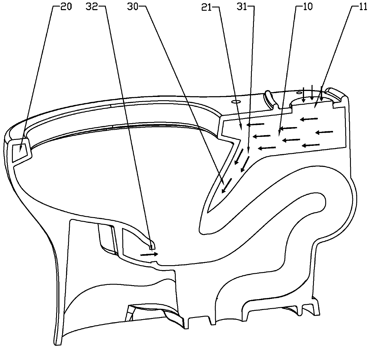
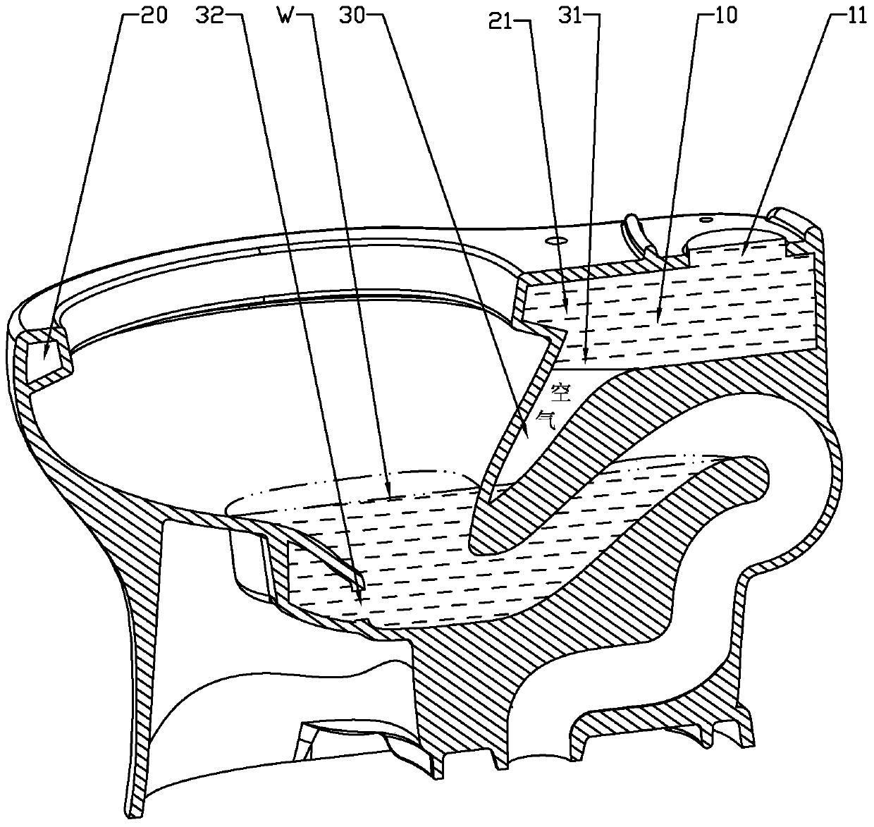
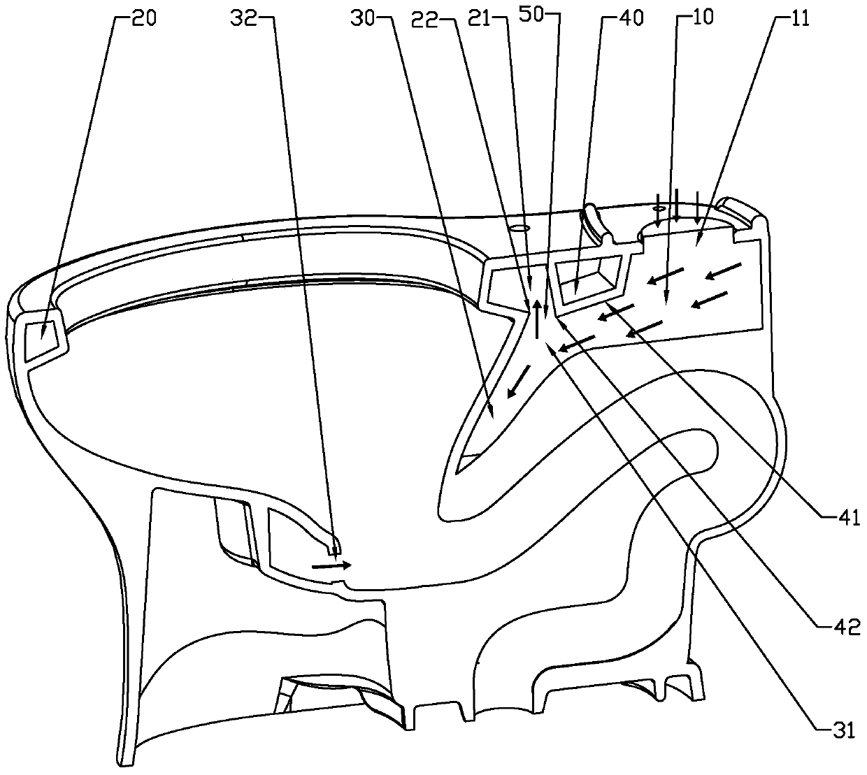
[0033] Such as image 3 and Figure 4 As shown, a kind of accelerated siphon toilet flushing waterway structure of the present invention includes a shared waterway 10 located in the toilet seat, a waterway 20 for supplying water to the toilet rim, and a waterway 20 for supplying water to the toilet spray port 32 The spray waterway 30, the front end of the shared waterway 10 communicates with the water inlet 11 of the toilet seat, the rear end of the shared waterway 10 forms a shunt and communicates with the inlet end 21 of the rim washing waterway 20 a...


PUM


Abstract

The invention discloses a closestool washing water way structure capable of accelerating siphon and a toilet seat. The closestool washing water way structure comprises a common water way arranged in the toilet seat, a washing ring water way for providing water to a closestool washing ring, and a spray water way for providing water to a closestool spray hole, wherein the front end of the common water way is communicated with a water inlet of the toilet seat, the rear end of the common water way forms split-flows and is respectively communicated with an inlet end of the washing ring water way and an inlet end of the spray water way, the common water way is internally provided with a flow guide structure for preferentially guiding the water flow into the spray water way, so that most of the air in the spray water way enters the washing ring water way and is exhausted from a washing ring hole along the washing ring water way before washing is carried out, therefore, the influences of the air to the potential energy of the water flow is reduced, the exhausting speed of the air in the spray water way is improved, the early formation of spray siphon is facilitated, and the water use amount for washing is reduced.

Description

technical field [0001] The invention relates to the technical field of sanitary ware, in particular to a toilet flushing waterway structure for accelerating siphon and a toilet seat with the flushing waterway structure. Background technique [0002] Many of the flushing waterways between the water inlet and the toilet bowl in the existing toilet seat body adopt a common waterway and two diversion waterways, such as figure 1 and figure 2 As shown, the two diverging waterways are the waterway 20 for supplying water to the rim on the top of the toilet seat and the jetting waterway 30 for supplying water to the jet port 32 at the bottom of the toilet bowl respectively, and the front end of the common waterway 10 communicates with the toilet The water inlet 11 of the pedestal, the rear end is divided into two strands, one flows out along the ring washing waterway 20, and the other flows out along the spraying waterway 30 downwards. [0003] The flushing water circuit in the to...

Claims


Application Information

Patent Timeline
Patent Type & Authority Patents(China)
IPC IPC(8): E03D9/16
CPCE03D9/16
Inventor 钟志军刘梓光陈海滨
Owner XIAMEN R&T PLUMBING TECH
Why Eureka
Try Eureka