Livestock bloodletting device with pushing device

A technology of pushing device and draining blood, applied in poultry processing, poultry processing support device, blood collection/blood stirring device, etc., can solve the problems of blood waste, slow blood draining process, and poultry turbulence, etc., to prevent clogging, speed up draining effect

Inactive Publication Date: 2018-04-20
ZHENGZHOU TIANSHUN ELECTRONICS TECH CO LTD
0 Cites 7 Cited by

AI-Extracted Technical Summary

Problems solved by technology

[0002] In the process of slaughtering poultry, because poultry turmoil often occurs in the process of slaughtering and draining blood, the blood is splashed around, which not only causes waste of blood, but also affects the surrounding environmental sanitation, and the blood cannot be well carried out. Unified collection and processing
[0003] The poultry bleeding devices currently appearing on the market are generally fixed and static. The bleeding process of this type of bleeding device is slow, and it takes a long time to complete the bleeding, and the bleeding is not very thorough, which greatly affects the production of the assembly line. Moreover, the poultry blood...

Abstract

The invention discloses a poultry bleeding device with a pushing device, which comprises a bleeding box, and the bleeding box is provided with a collection chamber and a bleeding chamber, the collection chamber is located at the bottom of the bleeding box, and the bleeding chamber is located in the collection chamber Above, a diversion slope is provided between the leach chamber and the collection chamber, and a filter screen is provided at the bottom of the diversion slope. A push motor is provided on the left wall of the leach box, and a push propeller is fixed on the push rod. The collection chamber The bottom of the right side wall is provided with an outlet vessel, the top of the right side wall of the collection chamber is provided with an observation port, the center of the top of the leach tank is equipped with a leach motor, the motor shaft of the leach motor is vertically fixed to the rotating rod, and the rotating rod is The suspension frame and the baffle are fixed, the bottom surface of the suspension frame is fixed with a hook, the bottom end of the rotating rod is fixed with a cleaning turntable and a cleaning brush, and a push door is rotated and fixed on the right side wall of the bleeding chamber; the present invention can realize centrifugal acceleration bleeding , Prevent poultry from leach blood pollution, prevent filter clogging and grind and push blood to discharge multiple functions.

Application Domain

Blood collection/stirring apparatusPoultry processing support devices

Technology Topic

Image

  • Livestock bloodletting device with pushing device
  • Livestock bloodletting device with pushing device
  • Livestock bloodletting device with pushing device

Examples

  • Experimental program(1)

Example Embodiment

[0018] The technical solutions in the embodiments of the present invention will be clearly and completely described below in conjunction with the accompanying drawings in the embodiments of the present invention. Obviously, the described embodiments are only a part of the embodiments of the present invention, rather than all the embodiments. Based on the embodiments of the present invention, all other embodiments obtained by those of ordinary skill in the art without creative work shall fall within the protection scope of the present invention.
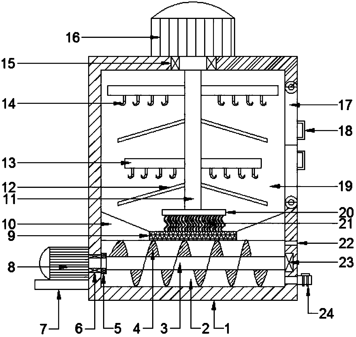
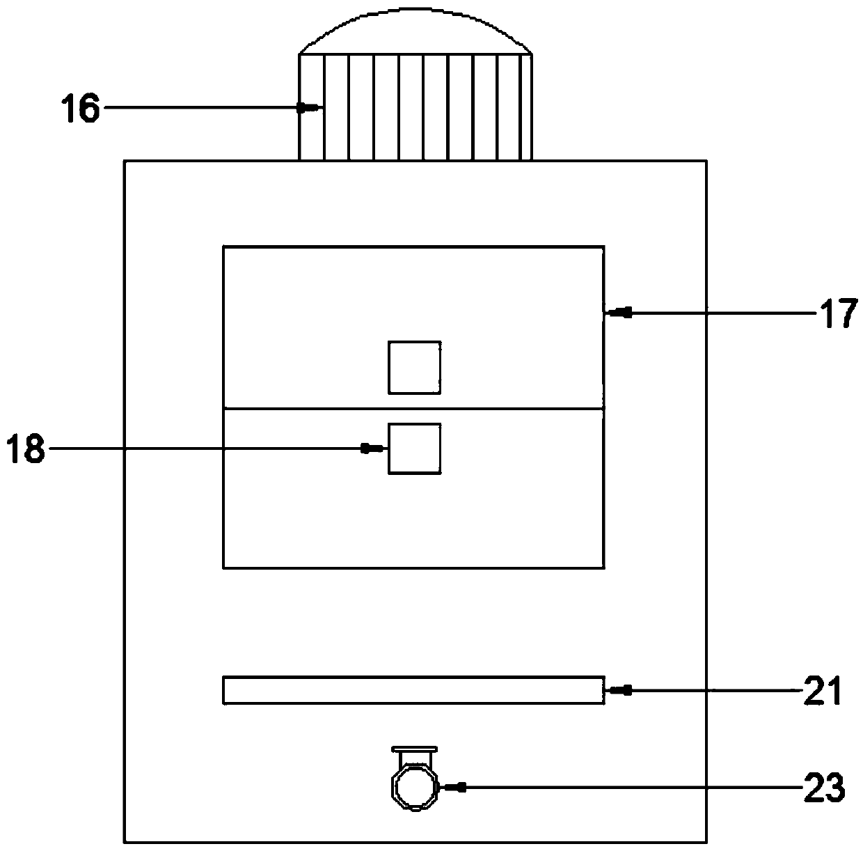
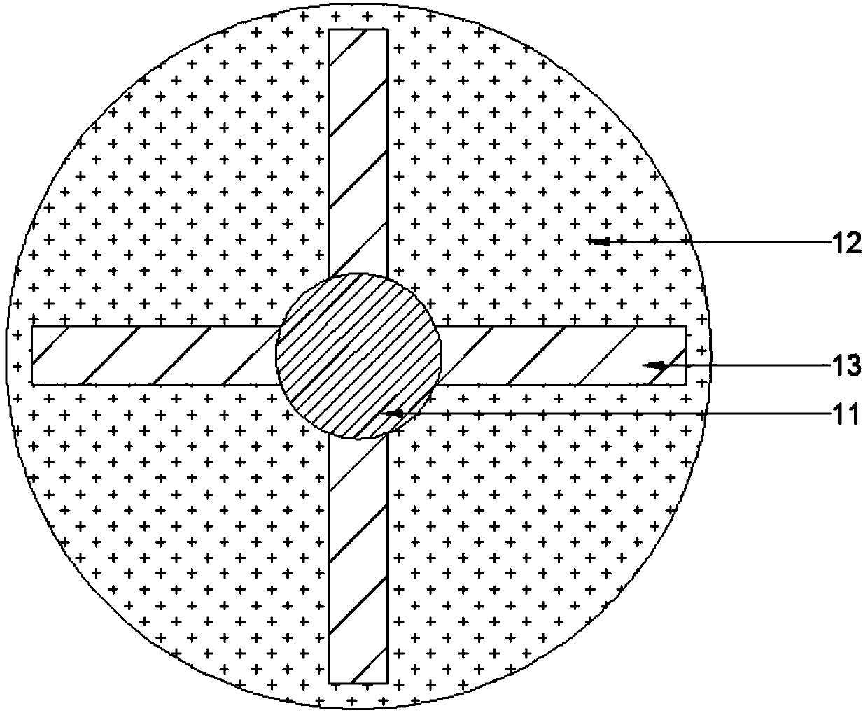
[0019] See Figure 1~3 In an embodiment of the present invention, a poultry blood draining device with a pushing device includes a blood drain box 1, a collection chamber 2, a pushing rotating rod 3, a pushing propeller 4, a blocking ring 5, a rotating bearing 6, a motor base 7, Push motor 8, filter screen 9, diversion slope 10, rotating rod 11, baffle 12, suspension frame 13, hook 14, bleeding bearing 15, bleeding motor 16, sliding door 17, pull ring 18, bleeding chamber 19 The cleaning turntable 20, the cleaning brush 21, the observation port 22, the support bearing 23, and the outlet vessel 24. The blood drain box 1 is provided with a collection room 2 and a blood drain room 19, and the collection room 2 is located in the blood drain box 1 At the bottom, the blood draining chamber 19 is located above the collecting chamber 2, a diversion slope 10 is provided between the blood draining chamber 19 and the collection chamber 2, the diversion slope 20 is funnel-shaped, and the diversion slope 20 is sloped A filter screen 9 is provided at the bottom. The filter screen 9 is made of edible stainless steel mesh. A motor base 7 is fixed on the left side wall of the blood drain box 1, and the pushing motor 8 is fixed on the motor base 7. The motor shaft of the pushing motor 8 penetrates the rotating bearing 6 to extend into the collection chamber 2. The rotating bearing 6 is provided on the left side wall of the collection chamber 2, and the right side of the rotating bearing 6 is provided with a blocking ring 5, so The plugging ring 5 is a rubber ring fixed on the motor shaft of the pushing motor 8. The motor shaft of the pushing motor 8 is fixedly connected to the pushing rod 3, and the pushing rod 3 is horizontally arranged in the collection chamber 2. The right end of the push rod 3 is rotatably fixed in a support bearing 23, the support bearing 23 is fixed on the inner wall of the collection chamber 2, and the push rod 3 is fixed with a push propeller 4, the screw of the push propeller 4 The blades are set to spiral to the right when the motor rotates forward, the bottom of the right side wall of the collection chamber 2 is provided with an outlet vessel 24, and an on-off valve is provided on the outlet vessel 24. The right side of the collection chamber 2 An observation port 22 is provided on the top of the wall. The observation port 22 is made of glass and fixed in the right side wall of the collection chamber 2 with glue. The top center of the blood drain box 1 is installed with a blood drain motor 16 inverted. The motor shaft of the blood draining motor 16 penetrates the blood draining bearing 15 into the blood draining chamber 19, the blood draining bearing 15 is fixed at the top center of the blood draining chamber 19, and the motor shaft of the blood draining motor 16 is fixed vertically The rotating rod 11 is fixed to the suspension frame 13 and the baffle 12, the width of the suspension frame 13 decreases from top to bottom, the bottom surface of the suspension frame 13 is fixed with a hook 14 and the baffle 12 Fixed under each suspension frame 13, the baffle 12 is an inverted funnel-shaped stainless steel plate cover, the bottom end of the rotating rod 11 is fixed with a cleaning turntable 20, the bottom of the cleaning turntable 20 is fixed with a cleaning brush 21, so A sliding door 17 is rotatably fixed on the right side wall of the bleeding chamber 19, and a pull ring 18 is fixed on the outer side wall of the sliding door 17.
[0020] The working principle of the present invention is: when working, first open the push door 17, and then hang the poultry that needs to be slaughtered upside down on the hook 14. When the hanging is full, close the push door 17, the strong blood drain motor 16, the blood drain motor 16 The rotating rod 11 in the blood drain chamber 19 is driven to rotate, and the poultry hanging upside down on the suspension frame 13 quickly drains blood from the body under the action of the rotating centrifugal force. Among them, the setting of the baffle 12 can prevent the blood dripping from the suspension frame 13 Spilled on the surface of poultry, the drained blood will flow along the baffle 12 to the diversion slope 10, and then through the filter 9 to enter the collection chamber 2, through the observation port 22 to determine whether the blood in the collection chamber 2 is collected When the collection is full, open the on-off valve of the push motor 8 and the outlet vessel 24, and the push rod 3 will drive the push propeller 4 to rotate forward. While rotating and stirring the blood, the blood clots that are still standing in it are minced while the blood It is pushed to the outlet vessel 24 on the right side of the collection chamber 2 and discharged, thereby completing the whole process of centrifugal bleeding, diversion and filtration, and crushing, pushing and discharging.
[0021] For those skilled in the art, it is obvious that the present invention is not limited to the details of the foregoing exemplary embodiments, and the present invention can be implemented in other specific forms without departing from the spirit or basic characteristics of the present invention. Therefore, from any point of view, the embodiments should be regarded as exemplary and non-limiting. The scope of the present invention is defined by the appended claims rather than the above description, and therefore it is intended to fall within the claims. All changes within the meaning and scope of equivalent elements of are included in the present invention. Any reference signs in the claims should not be regarded as limiting the claims involved.
[0022] In addition, it should be understood that although this specification is described in accordance with the implementation manners, not each implementation manner only includes an independent technical solution. This narration in the specification is only for clarity, and those skilled in the art should consider the specification as a whole The technical solutions in the embodiments can also be appropriately combined to form other implementations that can be understood by those skilled in the art.

PUM

no PUM

Description & Claims & Application Information

We can also present the details of the Description, Claims and Application information to help users get a comprehensive understanding of the technical details of the patent, such as background art, summary of invention, brief description of drawings, description of embodiments, and other original content. On the other hand, users can also determine the specific scope of protection of the technology through the list of claims; as well as understand the changes in the life cycle of the technology with the presentation of the patent timeline. Login to view more.

Similar technology patents

Classification and recommendation of technical efficacy words

  • Avoid clogging
  • Speed up discharge

Drainage system for municipal roads

InactiveCN111075005AIncrease flow path and flowSpeed ​​up dischargeFatty/oily/floating substances removal devicesSewerage structuresFootpathDrainage ditch
Owner:建信项目管理有限公司
Why Eureka
Try Eureka