
A Combined Miniature Foil Gas Dynamic Pressure Bearing

A gas dynamic pressure bearing, combined technology, applied in the direction of sliding contact bearings, rotating bearings, bearings, etc., can solve the bearing capacity and installation limitations of micro gas bearings, it is difficult to ensure dimensional accuracy and geometric accuracy, bearing design analysis difficulties and other problems, to achieve the effect of easy take-off, increased rigidity, and small bearing rigidity

Active Publication Date: 2018-06-26
HUNAN UNIV
View PDF7 Cites 0 Cited by
  • Summary
  • Abstract
  • Description
  • Claims
  • Application Information

AI Technical Summary

Problems solved by technology

In fact, due to the small size of miniature gas bearings, some parts are difficult to process, such as corrugated foils. overall performance analysis
Secondly, since the thickness of the air film is generally several microns to tens of microns, it is necessary to consider the air thinning effect, speed slip and gas viscosity changes, which brings great difficulties to the bearing design analysis.
Under the premise of processing with LIGA technology, the thickness of the bearing generally does not exceed one millimeter. Therefore, the load-bearing capacity and installation of the micro-air bearing are also limited.

Method used


Image

  • A Combined Miniature Foil Gas Dynamic Pressure Bearing
  • A Combined Miniature Foil Gas Dynamic Pressure Bearing
  • A Combined Miniature Foil Gas Dynamic Pressure Bearing

Examples


Embodiment Construction

[0029] The embodiments of the present invention will be further described below in conjunction with the drawings and examples. It should be noted that the embodiments do not limit the scope of protection claimed by the present invention.

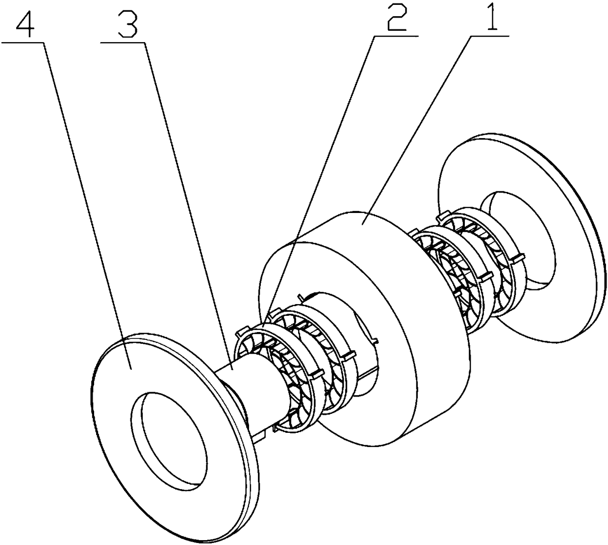
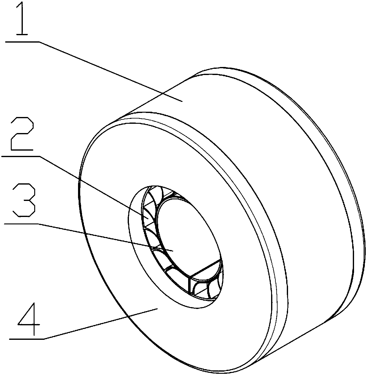
[0030] Such as figure 1 , figure 2 As shown, a combined micro-foil aerodynamic bearing includes a bearing body 1, an elastic foil support structure 2 arranged in the bearing body 1, a top layer foil 3 arranged in the elastic foil support structure 2, and a bearing The end face gland 4 glued symmetrically on both sides of the body 1.

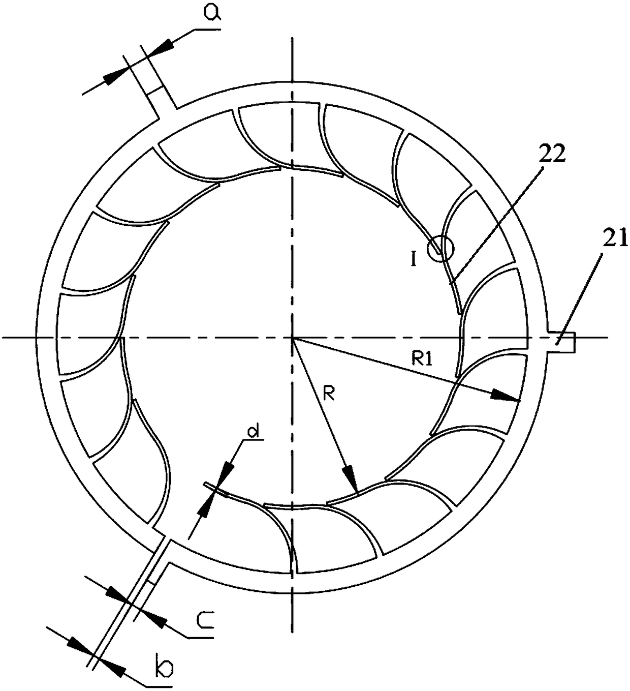
[0031] Such as Figure 3-Figure 9 As shown, the bearing body 1 is provided with an axial groove 11; the outer wall of the elastic foil support structure 2 is provided with a spline tooth structure 21, and the plurality of elastic foil support structures 2 are embedded through the spline tooth structure 21 The axial groove 11 on the bearing body 1 forms a circumferential positioning with the bearing body 1 ...


PUM


Abstract

The invention discloses a combined mini-type foil gas dynamic pressure bearing. The combined mini-type foil gas dynamic pressure bearing comprises a bearing body (1), end face glands (4) arranged at the two sides of the bearing body (1), multiple elastic foil supporting structures (2) and top foil (3), wherein the multiple elastic foil supporting structures (2) are fixedly arranged on the inner wall of the bearing body (1); the top foil (3) is attached to the inner sides of the multiple elastic foil supporting structures (2) and fixed to the inner wall of the bearing body (1) through a foil outwards-extending part (31). The combined mode is adopted, so that the bearing capacity of the mini-type gas bearing is improved, and installation is more convenient. Meanwhile, the reasonable elastic supporting structures are adopted, the starting stiffness is small, the stiffness is greatly increased as the rotation speed is increased, and the stability and shock resistance are improved.

Description

technical field [0001] The invention relates to the technical field of air bearings, in particular to a combined micro-foil gas dynamic pressure bearing. Background technique [0002] Air foil dynamic pressure bearing is a kind of dynamic pressure bearing that uses foil as elastic supporting element and air as lubricant. It is mainly divided into cantilever type, winding type, outer wedge type and corrugated foil type. Since there is no mechanical contact during operation, the friction and wear between the rotor and the bearing is reduced, which can provide extremely high precision. The use of air lubrication can slow down the temperature rise and effectively prolong the life of the bearing. The dynamic pressure bearing runs smoothly and has good vibration resistance. Among them, the foil dynamic pressure bearing uses foil as the elastic support element. With its structural characteristics, it has a certain rigidity and damping, so that the bearing has better carrying capac...

Claims


Application Information

Patent Timeline
Patent Type & Authority Patents(China)
IPC IPC(8): F16C17/12
CPCF16C17/12
Inventor 冯凯张敏李文俊程苗苗
Owner HUNAN UNIV
Learn More