A field sensor calibration system and method

A calibration system and sensor technology, applied in the direction of instruments, electromagnetic field characteristics, measuring devices, etc., can solve the problems of large influence of field distribution in the calibration area and small calibration area

Active Publication Date: 2019-02-15
BEIJING INST OF RADIO METROLOGY & MEASUREMENT
View PDF5 Cites 0 Cited by
  • Summary
  • Abstract
  • Description
  • Claims
  • Application Information

AI Technical Summary

Problems solved by technology

[0005] The invention proposes a field sensor calibration system and method, which solves the problem that the calibration area is small and the field sensor has a great influence on the field distribution in the calibration area, and improves the calibration accuracy of the field sensor

Method used


Image

  • A field sensor calibration system and method
  • A field sensor calibration system and method
  • A field sensor calibration system and method

Examples


Embodiment Construction

[0023] In order to achieve the object of the present invention, an embodiment of the present invention provides a field sensor calibration system and method, which aims to reduce the influence of the field sensor on the field distribution inside the calibration area and improve the calibration accuracy of the field sensor. Various embodiments of the present invention will be further described in detail below in conjunction with the accompanying drawings. Apparently, the described embodiments are only some of the embodiments of the present invention, not all of them. Based on the embodiments of the present invention, all other embodiments obtained by persons of ordinary skill in the art without making creative efforts belong to the protection scope of the present invention.

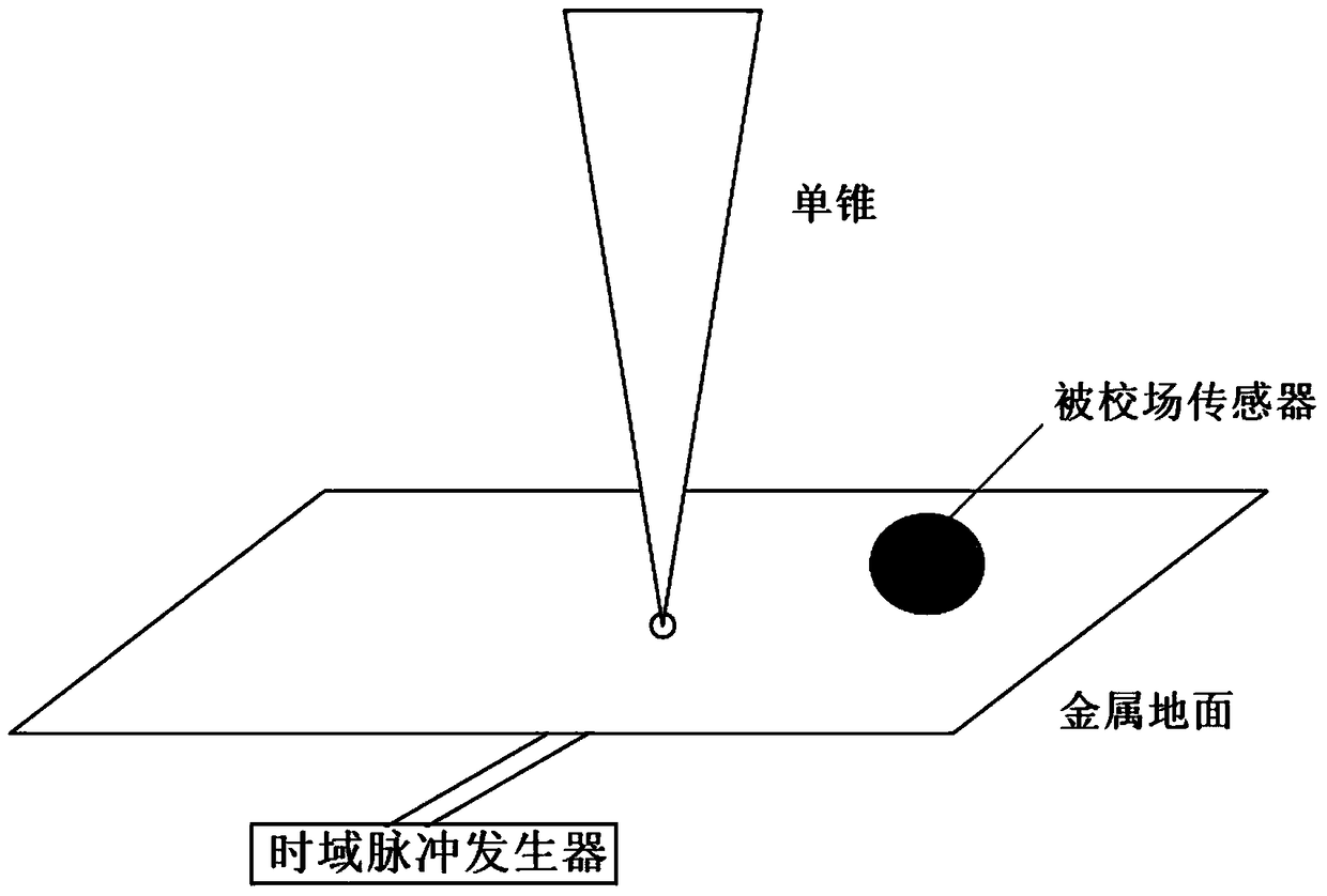
[0024] figure 1 It is a schematic diagram of a calibration system combined with a single cone and a metal ground in the prior art, and the calibration system includes a single cone structure, a metal grou...


PUM


Abstract

The invention provides a field sensor calibration system and a method, and the problems of a small calibration area and large influence on field distribution by a field sensor are solved. The field sensor calibration system comprises a single cone body and a flat plane body, and a single cone body antenna is formed. The single cone body is gradually narrowed from a top surface to a bottom surface, and the rotation curve shape of a side face is an exponential curve. According to the field sensor calibration method, firstly the single cone body antenna is set and is gradually narrowed from the top surface to the bottom surface, thus the space area used by the field sensor calibration is enlarged; a cube calibration area is defined in the range of single cone body antenna radiation, the vertex and each side middle point of the cube are provided with reference points, the electric field intensities of each reference point in the conditions with the field sensor and without the field sensor are calculated and compared, and the influence of the field sensor on the field distribution in the calibration area is obtained. The single cone body antenna impedance transformation method of the present invention is in the form of exponential transform, and the calibration precision of the field sensor is improved.

Description

technical field [0001] The invention relates to the field of electromagnetic field testing, in particular to a field sensor calibration system and method. Background technique [0002] At present, electromagnetic pulse field sensors are generally used for the measurement of pulsed fields at home and abroad. The pulse rise time and duration of ultra-broadband short-pulse electromagnetic fields are on the order of ns or shorter, and the spectrum width coverage is tens of MHz or wider, so it is difficult to measure. In order to ensure the accuracy of the electromagnetic pulse field strength measurement, it is necessary to perform performance calibration on the electromagnetic pulse field sensor in the time domain. [0003] The difficulty of time-domain calibration is to obtain the known field of the time-domain pulse field, that is, the standard field. The electromagnetic field sensor and probe calibration standard IEEE Std1309-2005 provides a field sensor calibration system ...

Claims


Application Information

Patent Timeline
Patent Type & Authority Patents(China)
IPC IPC(8): G01R35/00H01Q1/36G01R29/08
CPCG01R29/08G01R35/00H01Q1/36
Inventor 康宁马永光杨金涛吴红森
Owner BEIJING INST OF RADIO METROLOGY & MEASUREMENT
Why Eureka
Try Eureka