

Battery-driven electronic device
An electronic equipment, battery-driven technology, applied in the direction of battery circuit device, battery, secondary battery charging/discharging, etc., can solve problems such as potential drop
- Summary
- Abstract
- Description
- Claims
- Application Information
AI Technical Summary
Problems solved by technology
Method used
Image


Examples
Embodiment approach 1
[0032] "The Composition of a Battery-Powered Vacuum Cleaner"
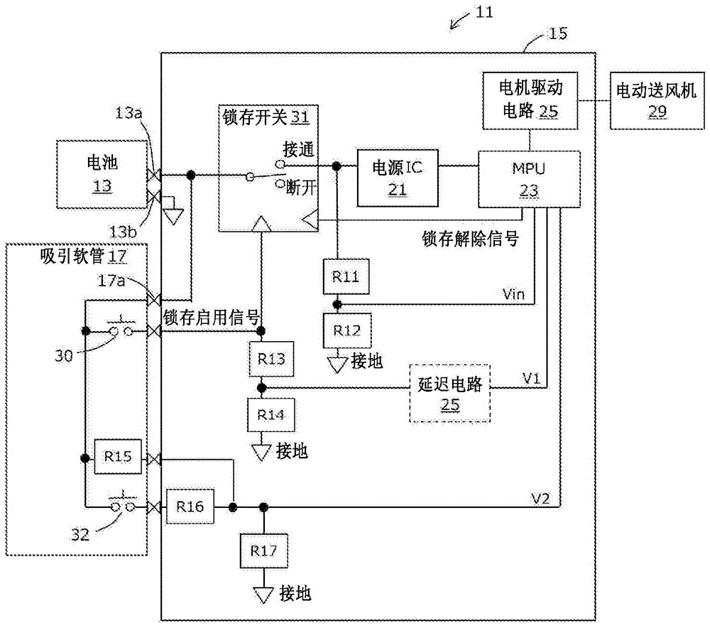
[0033] figure 1 It is explanatory drawing which shows the electrical structure of the battery-driven vacuum cleaner which is one form of the electronic equipment of this invention. For easy understanding, only the parts deeply related to the present invention are extracted, and some well-known elements are omitted. In this embodiment, the cleaner 11 is a canister cleaner, and is roughly divided into a cleaner main body, a suction hose 17 and a battery 13 . The battery 13 and the suction hose 17 are detachable from the vacuum cleaner main body, and are electrically connected via a connector. In addition, the battery 13 has battery terminals 13a and 13b, and is connected to the vacuum cleaner main body via the battery terminals 13a and 13b. The battery 13 is assumed to be a secondary battery such as a lithium ion battery, but is not limited thereto. The battery 13 may be accommodated in the vacuum cleaner main b...
Embodiment approach 2
[0069] illustrate figure 2 Different ways of installing the detection circuit are shown.
[0070] image 3 is indicated with the installation detection circuit of the present invention figure 2 Circuit diagrams of different configuration examples.
[0071] exist image 3 In the circuit shown, remove the figure 2 The equivalent part of the capacitor C33. Additionally, with Figure 8 Compared with Figure 8 The equivalent part of the capacitor C131. In addition, in image 3 in, right with figure 2 Corresponding circuit components are denoted by the same reference numerals.
[0072] As described in Embodiment 1, if the connection has the Figure 8 If a capacitor equivalent to C131 is used, when the battery 13 is installed and the emitter voltage of the transistor Q31 rises sharply, it is difficult to generate a potential difference between the emitter and the base of Q31. Therefore, it is difficult for Q31 to be turned on.
[0073] Conversely, just remove the Figur...
Embodiment approach 3
[0075] A still different way of installing the detection circuit is described.
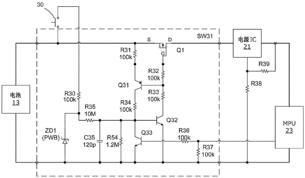
[0076] Figure 4 It is a circuit diagram showing still another different configuration example of the mounting detection circuit of the present invention.
[0077] and Figure 8 In contrast, it is different in that the capacitor C35 and the diode D1 are added. The cathode of diode D1 is connected to the base of transistor Q32, and the anode is connected to battery 13 via capacitor C35. The capacitor C35 forms a differential circuit with the diode D1, and responds to a voltage rise caused by attaching the battery 13 to the cleaner body.
[0078] That is, when the battery 13 is attached to the cleaner main body, the voltage is applied to the terminal of the capacitor C35 connected to the battery 13, and the voltage rises abruptly in a stepwise manner. Due to the capacitance component of the capacitor C35, this voltage increase causes the potential of the anode terminal of the diode D1 to increase...
PUM
 Abstract
Description
Claims
Application Information