Processing equipment for LCD backplanes for ultra-thin smartphones

A liquid crystal display and smart phone technology, which is applied in the field of processing devices for the backplane of ultra-thin smart phone liquid crystal displays, and achieves the effects of difficult product quality, good leveling effect and stable product quality.

Active Publication Date: 2017-10-20
KUNSHAN KERSEN SCI & TECH
View PDF6 Cites 0 Cited by
  • Summary
  • Abstract
  • Description
  • Claims
  • Application Information

AI Technical Summary

Problems solved by technology

[0003] Technical disadvantages: The jig corrects the defective products with flatness. Each adjustment can only correct the defective products with a certain range of flatness values. For the correction of defective products with different flatness values ​​in different ranges, the jig needs to be adjusted.

Method used


Image

  • Processing equipment for LCD backplanes for ultra-thin smartphones
  • Processing equipment for LCD backplanes for ultra-thin smartphones

Examples


Embodiment 1

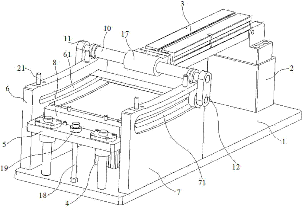
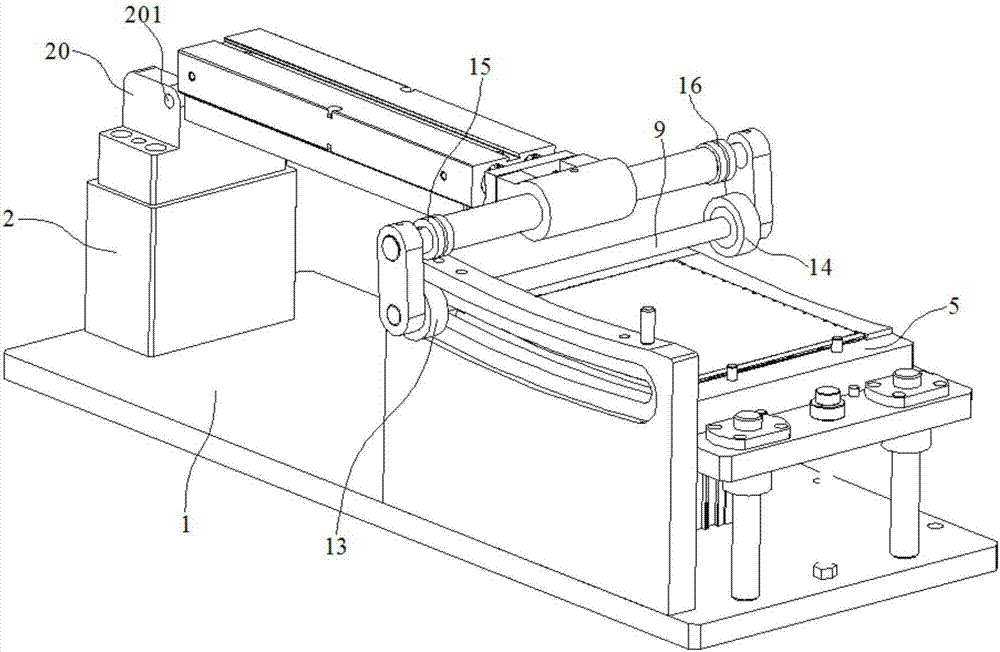
[0019] Embodiment 1: A processing device for the backplane of an ultra-thin smartphone liquid crystal display, including a bottom plate 1, a fixing seat 2, a horizontal cylinder 3, a vertical cylinder 4, a support plate 5 and a left guide rail fixed on the bottom plate 1 Seat 6, right guide rail seat 7, described support plate 5 is positioned between left guide rail seat 6, right guide rail seat 7, and a vertical cylinder 4 below support plate 5 is installed on the bottom plate 1 and the ejector rod of vertical cylinder 4 Connected with the support plate 5, the upper surface of the support plate 5 is covered with an elastic rubber pad 8;

[0020] Left through-hole bar 61 and right through-hole bar 71 are respectively opened on described left guide rail seat 6, right guide rail seat 7, and a rolling shaping rod 9 is positioned at support plate 5 tops and its two ends are respectively embedded in left through-hole bar 61, right In the through-hole bar 71, a connecting shaft 10 i...

Embodiment 2

[0025] Embodiment 2: A processing device for the backplane of an ultra-thin smartphone liquid crystal display, including a bottom plate 1, a fixing seat 2, a horizontal cylinder 3, a vertical cylinder 4, a support plate 5 and a left guide rail fixed on the bottom plate 1 Seat 6, right guide rail seat 7, described support plate 5 is positioned between left guide rail seat 6, right guide rail seat 7, and a vertical cylinder 4 below support plate 5 is installed on the bottom plate 1 and the ejector rod of vertical cylinder 4 Connected with the support plate 5, the upper surface of the support plate 5 is covered with an elastic rubber pad 8;

[0026] Left through-hole bar 61 and right through-hole bar 71 are respectively opened on described left guide rail seat 6, right guide rail seat 7, and a rolling shaping rod 9 is positioned at support plate 5 tops and its two ends are respectively embedded in left through-hole bar 61, right In the through-hole bar 71, a connecting shaft 10 i...


PUM


Abstract

The invention discloses a machining device for back plates of liquid crystal displays of ultra-thin smartphones. The machining device comprises a bottom plate, a fixed seat, a horizontal cylinder, a vertical cylinder, a support plate as well as a left guide rail seat and a right guide rail seat which are fixed on the bottom plate, wherein the support plate is located between the left guide rail seat and the right guide rail seat; the vertical cylinder located below the support plate is mounted on the bottom plate, an ejection rod of the vertical cylinder is connected with the support plate, and an elastomeric pad covers the upper surface of the support plate; a left through hole strip and a right through hole strip are formed in the left guide rail seat and the right guide rail seat respectively, a rolling shaping bar is located above the support plate, two ends of the rolling shaping bar are embedded in the left through hole strip and the right through hole strip, a connecting shaft is located on the left guide rail seat and the right guide rail seat, and two ends of the connecting shaft and the two ends of the rolling shaping bar are connected through a left connecting block and a right connecting block. With the adoption of the machining device, efficient and high-quality leveling operation can be realized for the back plates with large-range warpage, the leveling effect is good, the efficiency is high, and products have stable quality and cannot be broken easily.

Description

technical field [0001] The invention relates to the field of smart phone processing, in particular to a processing device for the backplane of an ultra-thin smart phone liquid crystal display. Background technique [0002] At present, the display backplanes of electronic products are mostly thin-plate stamping parts. In actual production, the flatness of thin-plate stamping parts is relatively high, and the poor flatness seriously affects the product yield. For products with complex processes, the finished product is scrapped due to flatness. Seriously affect the company's efficiency and waste social resources. Therefore, it is necessary to correct the flatness of the defective flatness products. [0003] Technical disadvantages: The jig corrects the defective products with flatness. Each adjustment can only correct the defective products with a certain range of flatness values. For the correction of defective products with different flatness values ​​in multiple ranges, th...

Claims


Application Information

Patent Timeline
Patent Type & Authority Patents(China)
IPC IPC(8): B21D1/02
CPCB21D1/02
Inventor 徐金根胡庆华李志勇
Owner KUNSHAN KERSEN SCI & TECH
Why Eureka
Try Eureka