Method for manufacturing an electromechanical transducer

a manufacturing method and electromechanical technology, applied in the field of electromechanical transducers, can solve the problems of uneven formation, limited flatness of the substrate surface, lowering of the performance of the cmut, etc., and achieve the effect of increasing the number of cells in the element of the electromechanical transducer, not impaired by flatness, and improving the flatness of the electroconductive substra

Inactive Publication Date: 2015-10-20
CANON KK
View PDF13 Cites 0 Cited by
  • Summary
  • Abstract
  • Description
  • Claims
  • Application Information

AI Technical Summary

Benefits of technology

[0010]According to the present invention, an electromechanical transducer is formed while using an electroconductive substrate as an electrode, after having ensured an electric connection between the electroconductive substrate and a through wiring, by obtaining a structure in which an insulative portion having a through hole is bonded onto the electroconductive substrate, and then filling the through hole with an electroconductive material to form the through wiring. Consequently, the electroconductive substrate can be used as the electrode in such a state that the flatness of the electroconductive substrate is not impaired, and consequently by using the electroconductive substrate of which the precision of the flatness has been guaranteed, the cell can be arranged even right on the through wiring, without being affected by a step between the through wiring and the insulative portion. Consequently, since the cell can be arranged even right on the through wiring, the number of cells arranged in the element of the electromechanical transducer can be increased, thereby the fill factor is enhanced, which leads to the enhancement of the performance. In addition, the dispersion among the cells can be decreased. Furthermore, since the cell which is structurally weak due to fine gaps therein is formed after the through wiring has been formed, the lowering of the yield can be reduced.

Problems solved by technology

Even if it is tried to flatten the surface with a Chemical Mechanical Polishing (CMP) process or the like, there is a limitation in flatness of the surface of the substrate due to a difference between the materials.
When the cells are arranged on the substrate having the steps, the lower electrode, the gap, the vibrating membrane and the upper electrode occasionally result in being unevenly formed as a result of receiving the influence of the steps.
Consequently, characteristics of the cell become different between a portion having the through wiring therein and a portion having no through wiring therein, which leads to the lowering of the performance of the CMUT.
On the other hand, in the latter method, since the through wiring is prepared after the element substrate has been prepared, it is difficult to arrange the cell right on the through wiring because of limitation by the manufacturing process.
Furthermore, since the cell is formed of a thin film which is structurally weak, there is a possibility that a yield decreases in an operation of forming the through wiring.

Method used


Image

  • Method for manufacturing an electromechanical transducer
  • Method for manufacturing an electromechanical transducer
  • Method for manufacturing an electromechanical transducer

Examples


exemplary embodiment 1

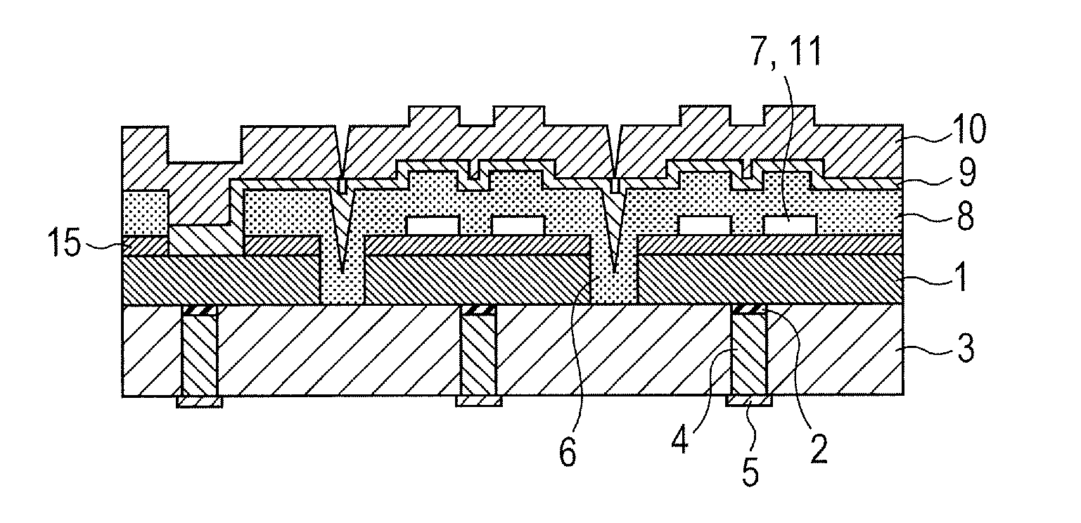
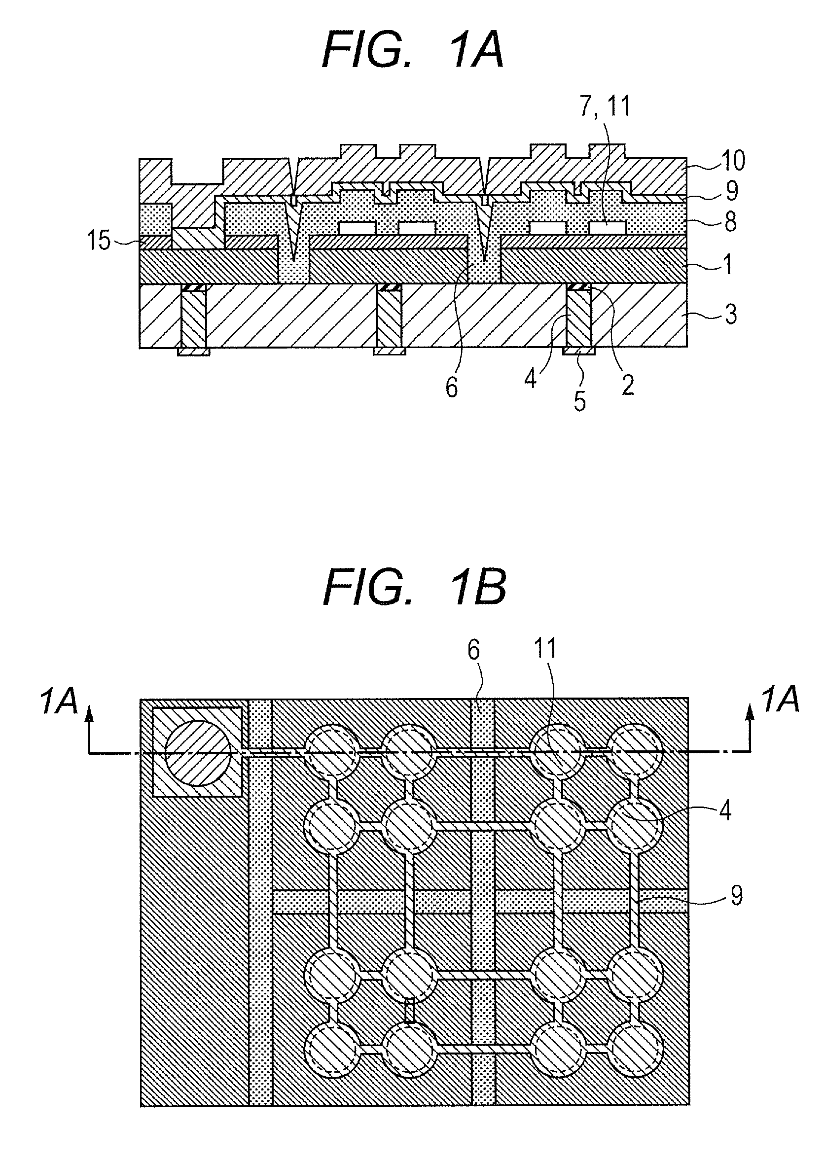
[0028]The exemplary embodiment 1 is concerned to a method for manufacturing the CMUT that is produced on a substrate which is formed of a low-resistance Si substrate and an insulative glass substrate and to which a through wiring is connected. Although a Pyrex (registered trademark) glass is used as an insulative substrate 3 provided with a through hole in the present exemplary embodiment, a basic manufacturing method is the same even when another material such as quartz glass is used.

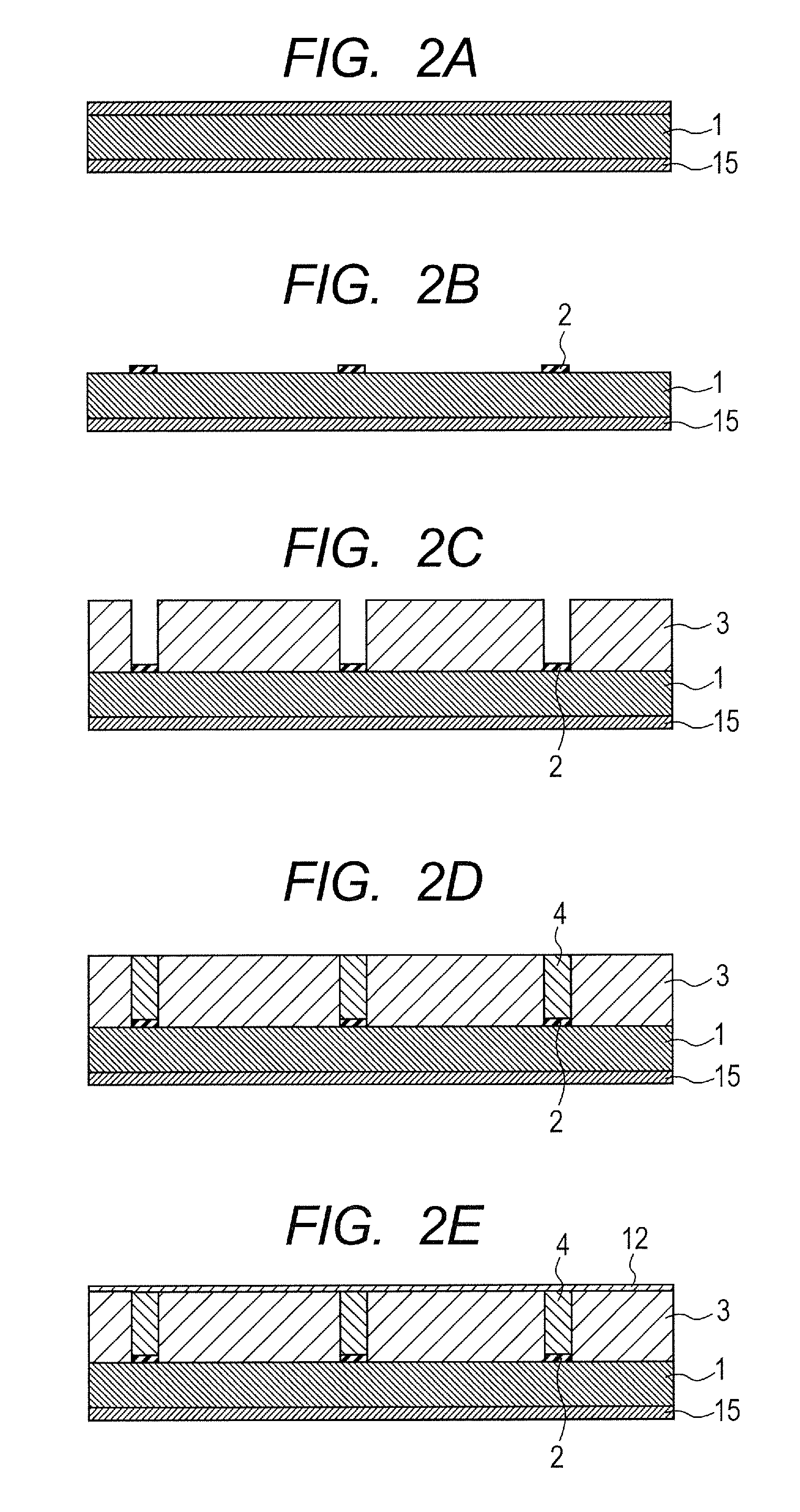
[0029]FIGS. 2A to 2M are views for describing a process flow of the present exemplary embodiment. Although a cross section of a device having two elements is illustrated in these views for simplification of the drawings, other elements can also be produced in a similar way. Firstly, an Si substrate which becomes a substrate 1 is prepared (FIG. 2A). Since the substrate 1 serves also as a first electrode which becomes a lower electrode, it is desirably a substrate having a low resistivity. In the present...

exemplary embodiment 2

[0042]In a manufacturing method of Exemplary Embodiment 2, an insulative member which is an insulating layer is formed by applying a resin or a glass material having photosensitive characteristics onto a low-resistance Si substrate. Then, by patterning a through hole in the insulative member, a structure of a substrate to which a through wiring is connected is prepared, and CMUT is produced on the structure.

[0043]In the present exemplary embodiment, polyimide (commercially available product made by Toray Industries, Inc., Asahi Kasei Corporation, Hitachi Chemical Company, Ltd. or the like) is used as a photosensitive resin material. Although the polyimide is used here as the photosensitive resin material, KI-1000 series (made by Hitachi Chemical Company, Ltd.), TMMR (made by TOKYO OHKA KOGYO CO., LTD.), SU-8 (made by Kayaku MicroChem Corporation) and the like can also be used. Furthermore, a photosensitive dry film (commercial product made by Hitachi, Ltd., Asahi Kasei Corporation, ...


PUM

PropertyMeasurementUnit
resistivityaaaaaaaaaa
surface roughness Rmsaaaaaaaaaa
thicknessaaaaaaaaaa

Abstract

The present invention provides a technology for decreasing a dispersion of the performance among electromechanical transducers each having through wiring. A method for manufacturing an electromechanical transducer includes: obtaining a structure in which an insulative portion having a through hole therein is bonded onto an electroconductive substrate; filling the through hole with an electroconductive material to form a through wiring which is electrically connected with the electroconductive substrate; and using the electroconductive substrate as a first electrode, forming a plurality of vibrating membrane portions including a second electrode, which opposes to the first electrode through a plurality of gaps, on an opposite side of the first electrode to the side having the insulative portion, to thereby forming a plurality of cells.

Description

BACKGROUND OF THE INVENTION[0001]1. Field of the Invention[0002]The present invention relates to an electromechanical transducer to be used for an ultrasound probe of an ultrasound diagnosis apparatus and the like, and to a method for manufacturing the same.[0003]2. Description of the Related Art[0004]An electromechanical transducer such as an ultrasound transducer conducts at least one of conversion from an electric signal to an ultrasound wave and conversion from the ultrasound to the electric signal, and it is used as a probe for ultrasound diagnosis for medical application, a probe for a non-destructive test and the like. In recent years, along with the development of a fine processing technology, a capacitance type electromechanical transducer (CMUT: Capasitive Micromachined Ultrasonic Transducer) produced by using the technology has been actively developed. An exemplary CMUT has a structure that an element substrate having a cell includes a substrate having a lower electrode (...

Claims


Application Information

Patent Timeline
Patent Type & Authority Patents(United States)
IPC IPC(8): H04R31/00H01G5/16H02N1/00
CPCH02N1/006H01G5/16Y10T29/43B06B1/0292
Inventor HASEGAWA, YOSHIHIROTAKAI, YASUYOSHI
Owner CANON KK
Why Eureka
Try Eureka