Die for punching of side edge of product with U-shaped section

A product and cross-section technology, applied in the field of auto parts production equipment, can solve the problems of low product hole size accuracy, inconvenient mold adjustment and product pick-and-place, low production efficiency, etc., to ensure product size accuracy and surface requirements, shorten adjustment The effect of reducing mold time and improving production efficiency

Active Publication Date: 2016-05-04
重庆宏协承汽车部件有限公司
View PDF7 Cites 0 Cited by
  • Summary
  • Abstract
  • Description
  • Claims
  • Application Information

AI Technical Summary

Problems solved by technology

[0002] The U-shaped cross-section automobile guide rail has a large output, and many require side punching. At this stage, most of the U-shaped cross-section automobile guide rails are punched on the side by drilling machines and milling machines, which makes the product production efficiency low. Die adjustment and pick-and-place products are difficult Inconvenient, the dimensional accuracy of the product hole is low, there are many burrs around the hole, the surface of the product is easy to scratch during the production process, and the customer has high requirements for the size and surface of the product. In order to solve the above problems, a Mold for side punching of U-shaped cross-section products

Method used


Image

  • Die for punching of side edge of product with U-shaped section
  • Die for punching of side edge of product with U-shaped section
  • Die for punching of side edge of product with U-shaped section

Examples


Embodiment

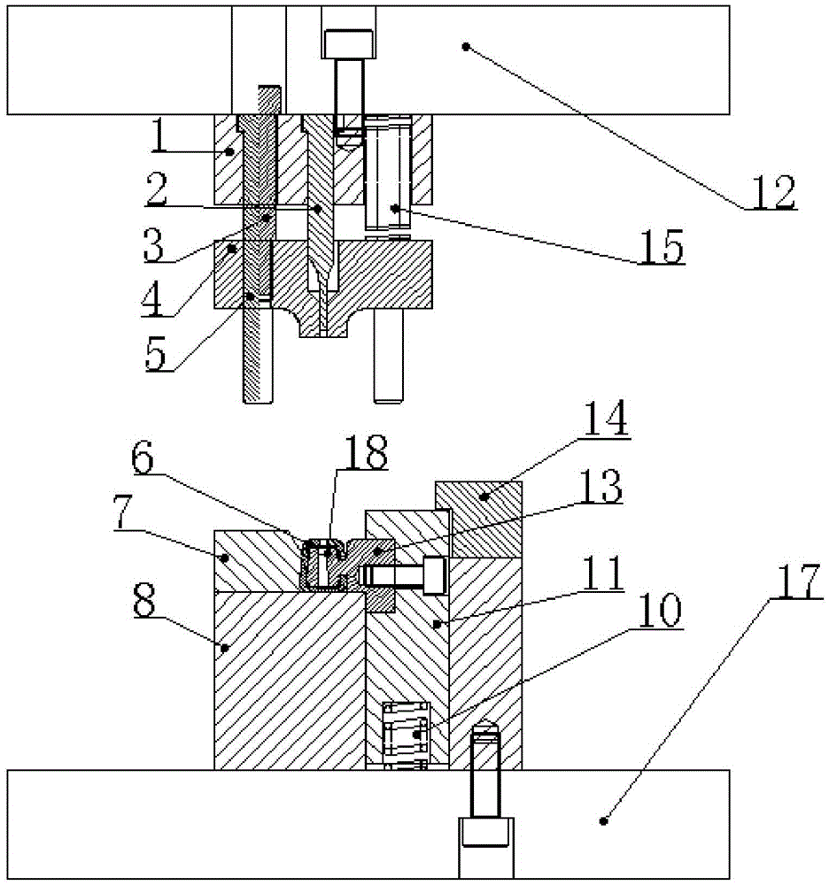
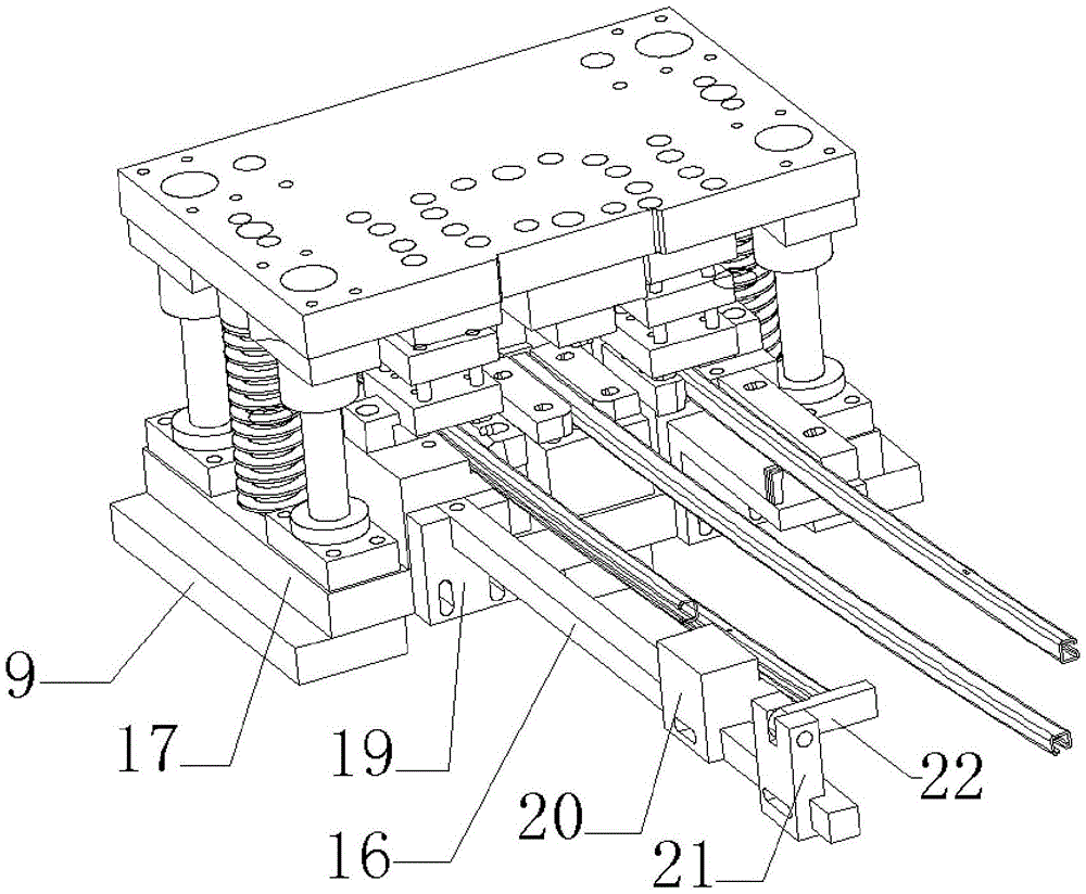
[0032] Place the mold as a whole on a 25T punch press, and rely on the up and down movement of the punch block to realize the up and down movement of the mold. First, the upward movement of the upper template 12 and the fixed plate 1 is controlled by a punching machine, and the unloading screw 3 slidably connected in the upper template 12 drives the unloading plate 4 to move upward together, and the unloading plate 4 is positioned with the die 13, the slider 11 and the side The block 7 is separated, and the compressed round wire coil spring 10 pushes the slider 11 and the die 13 to move upwards. After the upper end of the slider 11 bears against the horizontal part of the L-shaped limit block 14, it is moved along the die 13 from one side of the die. The product 6 is inserted until the front end of the product 6 withstands the baffle plate 22, then the punch press controls the upper template 12 and the fixed plate 1 to move downward, the unloading plate 4 contacts the die 13, a...


PUM


Abstract

The invention relates to a die for punching of a side edge of a product with a U-shaped section, comprising a male die, a female die and a lower die plate, wherein a lower die is arranged at the upper end of the lower die plate, a sliding block is arranged at one side of the lower die, the female die is arranged at the upper end of the lower die, a through hole is vertically formed in one end of the female die, the other end of the female die stretches into the side wall of the sliding block to be fixed, the lower die plate is connected with the sliding block by a round-wire spiral spring, the sliding block and the lower die are connected with a fixed plate arranged above the female die by an unloading guide pillar, an unloading plate capable of sliding along the unloading guide pillar is arranged between the fixed plate and the female die, the male die is arranged in the fixed plate, the lower end of the male die slides in a movable slot of the unloading plate, an upper die plate is arranged at the upper end of the fixed plate, an unloading screw is in sliding connection in the upper die plate, and the lower end of the unloading screw penetrates through the fixed plate to be connected with the unloading plate. The die can improve the production efficiency and ensure the dimension precision and surface requirements of products.

Description

technical field [0001] The invention relates to the field of auto parts production equipment, in particular to a mold for punching holes on the sides of U-shaped section products. Background technique [0002] The U-shaped cross-section automobile guide rail has a large output, and many require side punching. At this stage, most of the U-shaped cross-section automobile guide rails are punched on the side by drilling machines and milling machines, which makes the production efficiency of the product low. Inconvenient, the dimensional accuracy of the product hole is low, there are many burrs around the hole, the product surface is easy to scratch during the production process, and the customer has high requirements for the product size and surface. In order to solve the above problems, a The mold for punching holes on the side of U-shaped cross-section products. Contents of the invention [0003] The technical problem to be solved by the present invention is to provide a mo...

Claims


Application Information

Patent Timeline
Patent Type & Authority Applications(China)
IPC IPC(8): B21D28/34B21D28/32
CPCB21D28/32B21D28/34
Inventor 高永乐刘玉权
Owner 重庆宏协承汽车部件有限公司
Why Eureka
Try Eureka