Pressure relief system for pilot oil of oscillating cylinder hydraulic control valve

A technology of pilot oil and hydraulic control valve, applied in the field of hydraulic pressure, can solve problems such as pressure relief lag and affecting pumping efficiency, and achieve the effects of sufficient supply, difficult problems, and low cost

Inactive Publication Date: 2020-11-20
TIANJIN JIEQIANG POWER EQUIP
View PDF10 Cites 0 Cited by
  • Summary
  • Abstract
  • Description
  • Claims
  • Application Information

AI Technical Summary

Problems solved by technology

There is a design method of setting damping hole pressure relief, but the form of damping hole pressure relief will cause the pressure relief to lag and affect the pumping efficiency

Method used


Image

  • Pressure relief system for pilot oil of oscillating cylinder hydraulic control valve

Examples


Embodiment Construction

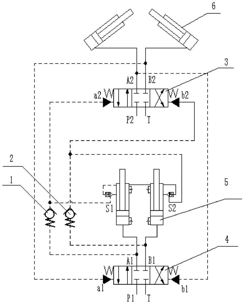
[0013] A pressure relief system for the pilot oil of a swing cylinder hydraulic control valve, which includes two swing cylinders 6, a swing cylinder hydraulic valve 3, two pumping cylinders 5 and a pumping cylinder hydraulic valve 4, two pumping cylinder hydraulic valves The oil outlets A1 and B1 are respectively connected with the oil inlets of the two pumping cylinders, and the oil returns of the two swing cylinders are respectively connected with the two oil return ports a1 and b1 of the hydraulic valves of the pumping cylinders through the oil return pipelines. The signal ports S1 and S2 of the pumping cylinder communicate with the two pilot oil ports a2 and b2 of the hydraulic valve of the swing cylinder respectively. A one-way valve 1, the inlet of the first one-way valve is connected to the pilot oil port a2 of the swing cylinder hydraulic valve and the signal port S1 of the pumping cylinder at the same time, the outlet is connected to the oil outlet A1 of the hydraulic...


PUM


Abstract

The invention relates to the technical field of hydraulics, and especially relates to a pressure relief system for pilot oil of an oscillating cylinder hydraulic control valve. The pressure relief system comprises two oscillating oil cylinders, an oscillating cylinder hydraulic valve, two pumping oil cylinders and a pumping oil cylinder hydraulic valve; a first one-way valve is arranged between anoil outlet A1 of the pumping oil cylinder hydraulic valve and a pilot oil port a2 of the oscillating cylinder hydraulic valve; an inlet of the first one-way valve is connected to the pilot oil port a2 of the oscillating cylinder hydraulic valve and a signal port S1 of the pumping oil cylinder at the same time, and an outlet of the first one-way valve is connected to the oil outlet A1 of the pumping oil cylinder hydraulic valve; a second one-way valve is arranged between an oil outlet B1 of the pumping oil cylinder hydraulic valve and a pilot oil port b2 of the oscillating cylinder hydraulic valve; and an inlet of the second one-way valve is connected to the pilot oil port b2 of the oscillating cylinder hydraulic valve and a signal port S2 of the pumping oil cylinder at the same time, andan outlet of the second one-way valve is connected with the oil outlet B1 of the pumping oil cylinder hydraulic valve. The system provided by the invention is simple in structure, low in cost and capable of achieving the pressure relief problem of the pilot oil by utilizing the pressure difference, and achieves the purpose of rapidly placing an oscillating cylinder in place.

Description

technical field [0001] The invention relates to the field of hydraulic technology, in particular to a pressure relief system for pilot oil of a swing cylinder hydraulic control valve. Background technique [0002] During the working process of the automatic pumping system, every action process of the swing cylinder needs to be in place quickly, so that the S valve in the hopper and the concrete cylinder can be seamlessly connected. In order to achieve this purpose, an accumulator is often installed in the hydraulic system to assist in the completion of the swing cylinder action, but the capacity of the accumulator is realized when the spool of the swing cylinder reversing valve is quickly shifted in place. At present, hydraulic control valves are used in large-displacement pumping systems. When one side of the hydraulic control valve receives a high-pressure pilot oil signal, how to quickly release the pressure of the pilot oil on the other side is particularly important. T...

Claims


Application Information

Patent Timeline
Patent Type & Authority Applications(China)
IPC IPC(8): F15B13/06F15B13/02
CPCF15B13/06F15B13/027
Inventor 赵敏杨震方郑家旺孟志强
Owner TIANJIN JIEQIANG POWER EQUIP
Why Eureka
Try Eureka