
Cutter sharpening rack

A technology of sharpening frame and support frame, which is applied in the direction of grinding frame, grinding bed, grinding slide plate, etc., can solve the problems of inconvenient sharpening, cleaning of iron filings, and scratching of operators by iron filings.

Active Publication Date: 2016-05-04
盐城项果科技有限公司
View PDF5 Cites 1 Cited by
  • Summary
  • Abstract
  • Description
  • Claims
  • Application Information

AI Technical Summary

Problems solved by technology

[0002] Inevitably, iron filings and dust will be generated during the sharpening process. However, it is impossible for the operator to clean the iron filings on the sharpening block from time to time. In this way, the iron filings are likely to scratch the operator during the sharpening process In addition, the existing sharpening block is limited by the position during the sharpening process, which brings inconvenience to the sharpening work

Method used


Image

  • Cutter sharpening rack

Examples


Embodiment Construction

[0023] Specific embodiments of the present invention will be described in detail below in conjunction with the accompanying drawings. It should be understood that the specific embodiments described here are only used to illustrate and explain the present invention, and are not intended to limit the present invention.

[0024] In the present invention, in the absence of a contrary statement, the orientation words included in the term such as "up, down, left, right, inside, outside" only represent the orientation of the term in the normal use state, or for the purpose of A common term understood by those skilled in the art, and should not be considered as a limitation of the term.

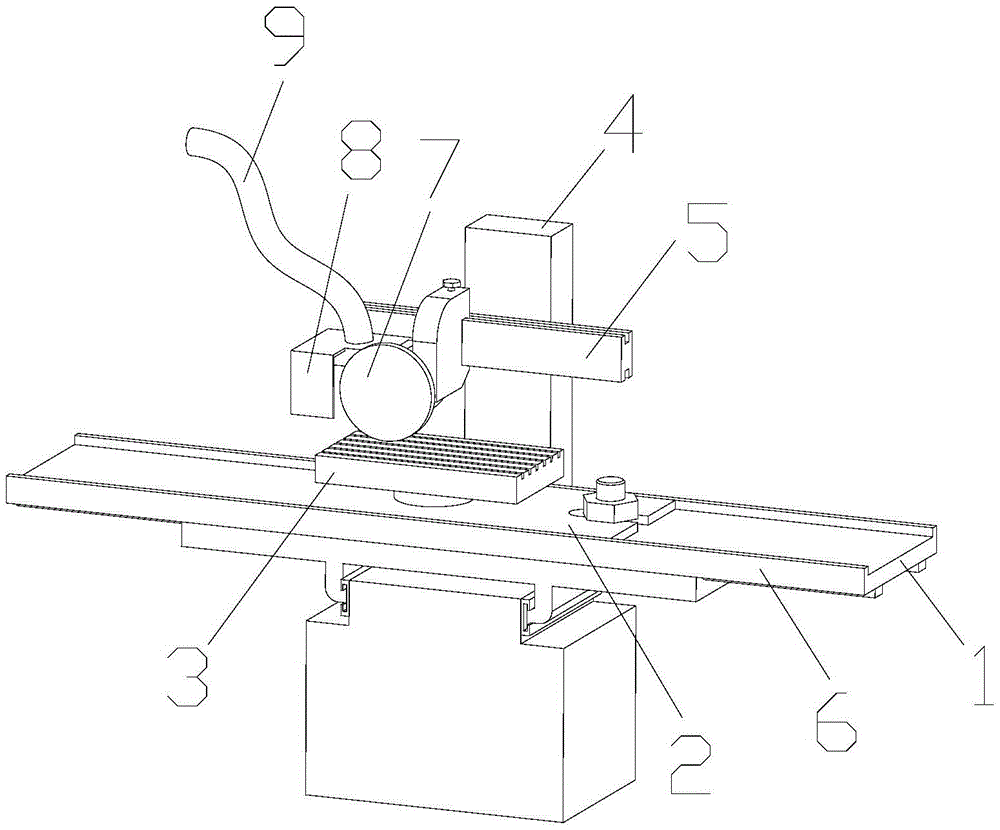
[0025] The invention provides a sharpening frame, such as figure 1 As shown, the sharpening frame includes a bottom plate 1, a sliding plate 2 detachably connected to the bottom plate 1, and a sharpening block 3 fixed on the sliding plate 2; the sharpening block 3 is provided with There are a plura...


PUM


Abstract

The invention discloses a cutter sharpening rack. The cutter sharpening rack comprises a bottom plate, a sliding plate which is detachably connected onto the bottom plate and a cutter sharpening block which is fixedly connected onto the sliding plate; multiple cutter sharpening grooves are formed in the cutter sharpening block; the cutter sharpening grooves are separately divided into first section grooves and second section grooves from the outer part to the inner part along the cutter sharpening block; and the groove opening widths of the first section grooves are larger than the groove opening widths of the second section grooves. According to the cutter sharpening rack, the hand of an operator cannot be scratched during a cutter sharpening process; and the operator can sharpen a cutter conveniently.

Description

technical field [0001] The invention relates to a knife sharpening device, in particular to a knife sharpening frame. Background technique [0002] Inevitably, iron filings and dust will be generated during the sharpening process. However, it is impossible for the operator to clean the iron filings on the sharpening block from time to time. In this way, the iron filings are likely to scratch the operator during the sharpening process In addition, the existing knife sharpening block is inconvenient to the sharpening work due to position restrictions during the knife sharpening process. [0003] Therefore, it is an urgent problem to be solved in the present invention to provide a knife sharpening frame that does not scratch the operator's hand during the knife sharpening process and is convenient for sharpening the knife. Contents of the invention [0004] The object of the present invention is to provide a knife sharpening frame which will not scratch the operator's hand d...

Claims


Application Information

Patent Timeline
Patent Type & Authority Applications(China)
IPC IPC(8): B24B3/36B24B41/02B24B55/00B08B5/04
CPCB08B5/04B24B3/36B24B41/02B24B55/00
Inventor 董武斌汪莉普天强朱勇彪章健刘阳黄晓剑
Owner 盐城项果科技有限公司
Learn More