Horizontal automatic flat die-cutting and creasing machine and its die-cutting method

A fully automatic, flattening technology, applied in the direction of object supply, metal processing, pile separation, etc., can solve the problems of large moment of inertia of the gripper row, the influence of die-cutting quality, and the difficulty of increasing the working speed of the machine, and achieve simplification. Gripper drive assembly, reducing mass and eliminating the effect of intermittent mechanism devices

Active Publication Date: 2018-02-23
广州高印力信息技术有限公司
View PDF8 Cites 0 Cited by
  • Summary
  • Abstract
  • Description
  • Claims
  • Application Information

AI Technical Summary

Problems solved by technology

The advantage of this kind of automatic die-cutting machine is that the die-cutting function is realized through the mechanical mechanism, and the crank-link mechanism can increase the force. There is no interference and collision between the jaws, the stroke of the moving platform is often relatively large (generally above 60mm), and the moment of inertia of the gripper jaws is also relatively large, and the working speed of the machine is not easy to increase (the domestic die-cutting machine is 7500 sheets / hour Below), in addition, in the prior art, in the die-cutting mechanism, the upper platform is a fixed platform, and the lower platform is a moving platform. In order to avoid collision with the gripper row, the stroke of the moving platform is often 60-70mm or even more Large, the paper hangs very high when passing the moving platform below, the movement of the moving platform itself will stir the air up and down, the movement of the gripper row and the paper will drive the air forward, and the strong turbulence of these airflows will cause the paper to flutter , which has a great influence on the die-cutting quality

Method used


Image

  • Horizontal automatic flat die-cutting and creasing machine and its die-cutting method
  • Horizontal automatic flat die-cutting and creasing machine and its die-cutting method
  • Horizontal automatic flat die-cutting and creasing machine and its die-cutting method

Examples


Embodiment Construction

[0039] The present invention will be described in further detail below in conjunction with the accompanying drawings.

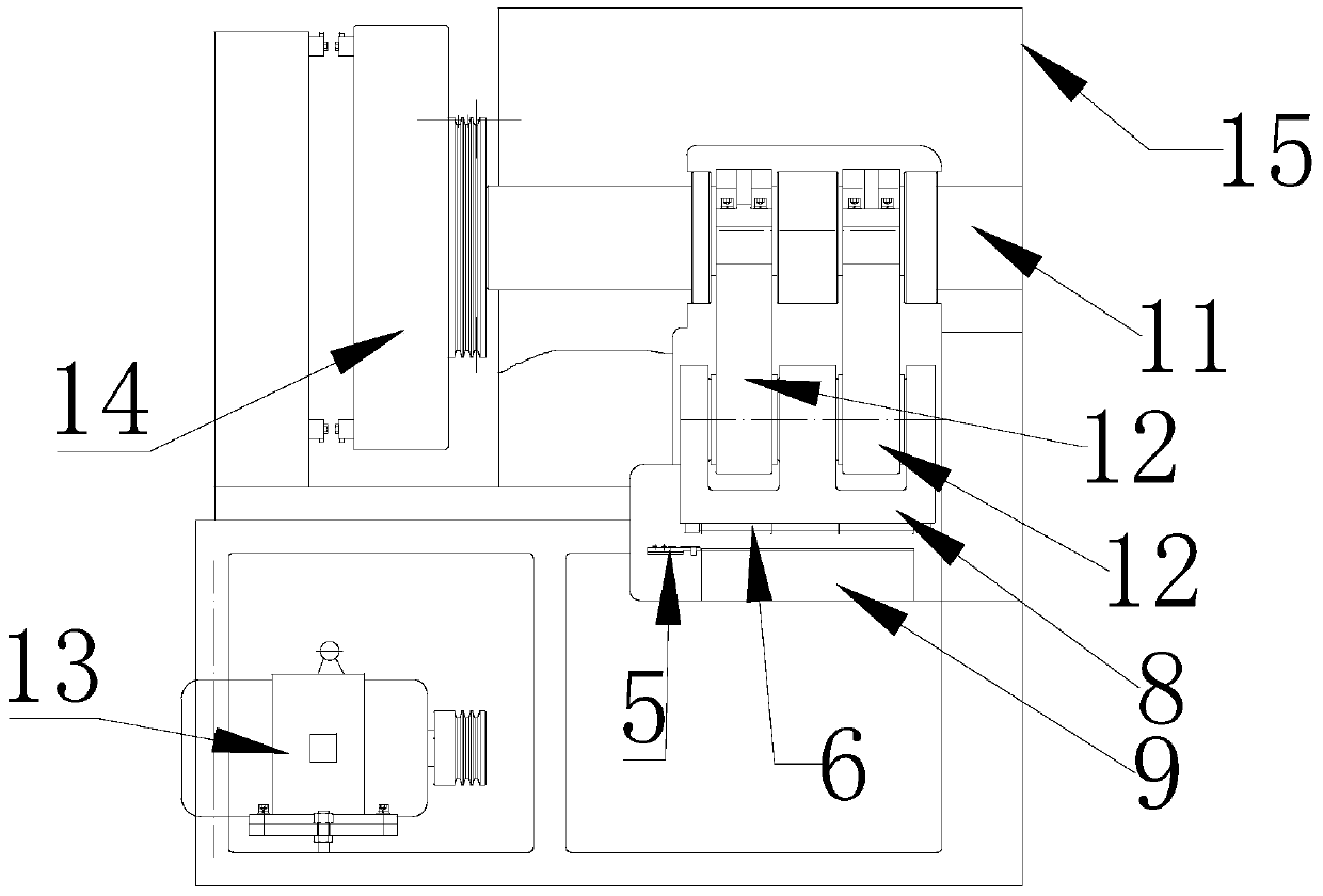
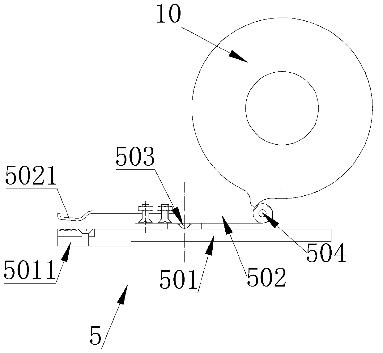
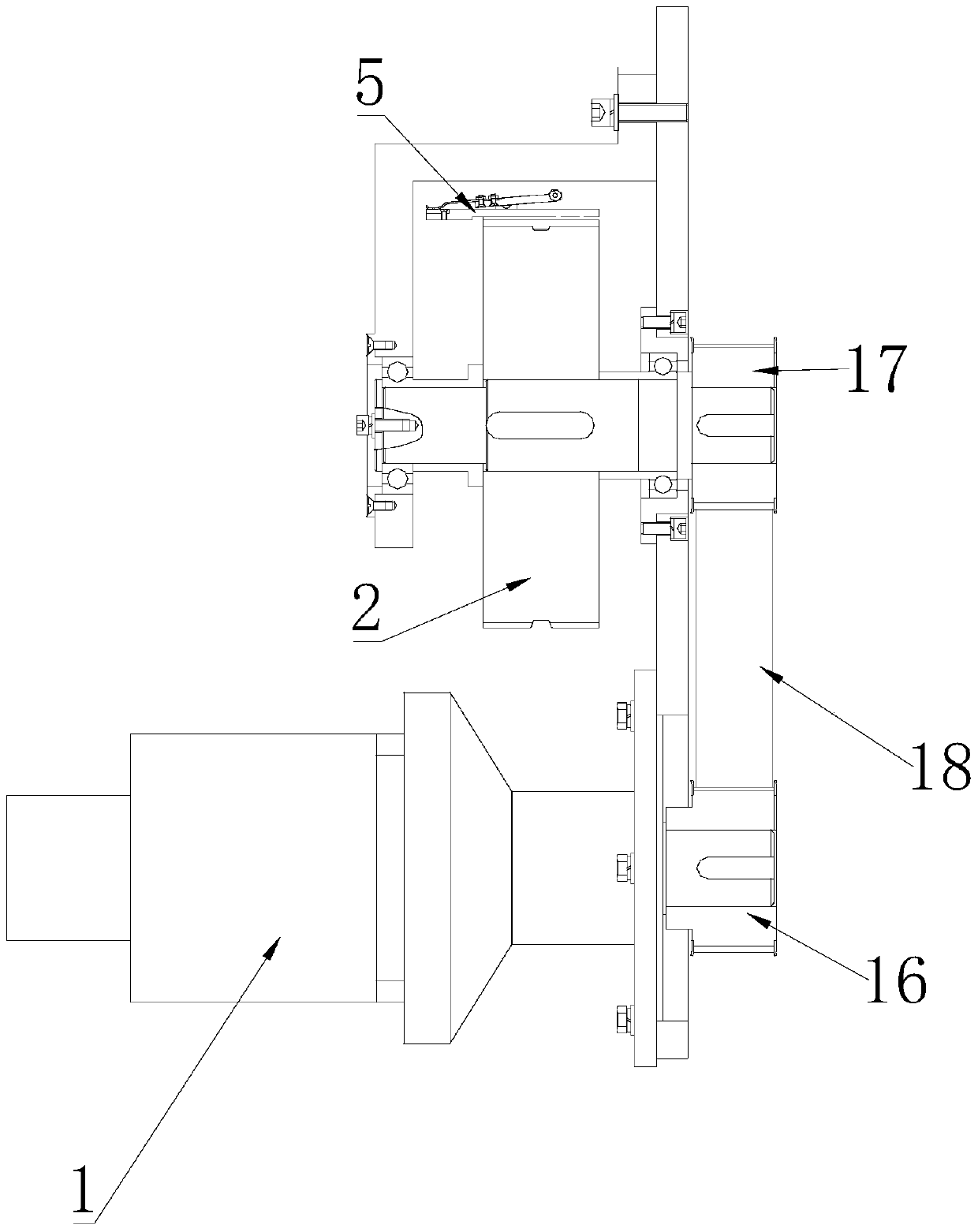
[0040] Figure 1 to Figure 7 A novel horizontal fully automatic flat die-cutting and creasing machine according to an embodiment of the present invention is schematically shown. As shown in the figure, a new type of horizontal fully automatic flat die-cutting and creasing machine is provided, including a frame 15, a paper feeding mechanism and a die-cutting mechanism installed on the frame 15, and the frame 15 is also provided with The main power mechanism and the die-cutting transmission mechanism are connected with the die-cutting transmission mechanism;

[0041] The die-cutting mechanism includes a movable platform 8 and a fixed platform 9, the movable platform 8 is connected with the die-cutting transmission mechanism, and the fixed platform 9 is fixed on the frame 15;

[0042] The paper feeding mechanism includes a gripper drive assembly, a gripper ope...


PUM


Abstract

The invention discloses a novel horizontal type full-automatic flat-pressing flat-die-cutting marking press and a die cutting method thereof. The marking press comprises a rack, a paper conveying mechanism and a die cutting mechanism, wherein the paper conveying mechanism and the die cutting mechanism are mounted on the rack; a main power mechanism and a die cutting transmission mechanism are further arranged on the rack and connected with each other. The paper conveying mechanism comprises a servo motor, a servo controller, a first synchronous pulley, a second synchronous pulley, a third synchronous pulley, a fourth synchronous pulley, a first synchronous belt, a second synchronous belt and a plurality of grippers, wherein the servo controller is connected with the servo motor, the third synchronous pulley is connected with a transmission shaft of the servo motor, and the second synchronous belt is mounted between the third synchronous pulley and the fourth synchronous pulley in a sleeving mode; the first synchronous pulley and the fourth synchronous pulley are connected, the first synchronous belt is mounted between the first synchronous pulley and the second synchronous pulley in a sleeving mode, and the grippers are arranged on the first synchronous pulley in a spaced mode. Accordingly, interference and collision between the grippers and a die cutting platform never occur, working efficiency is high, and the structure is simple.

Description

technical field [0001] The invention relates to the technical field of die-cutting equipment, in particular to a horizontal fully automatic flat die-cutting and creasing machine and a die-cutting method thereof. Background technique [0002] Die-cutting machine is one of the important equipments that use steel knives, steel wires (or stencils carved from steel plates) to roll-cut printed products or cardboards. In the existing automatic die-cutting machine, the upper platform equipped with the die-cutting blade is fixed, and the left-right symmetrical connecting rod, the upper swing rod and the lower swing rod are driven by the rotation of the crankshaft to drive the moving platform to move up and down to form the die-cutting stamping action; The main sprocket, the chain and the gripper row fixed on the chain realize the transmission of the job (such as paper), the paper stops during die-cutting, and the gripper row takes the paper away after the die-cutting is completed. T...

Claims


Application Information

Patent Timeline
Patent Type & Authority Patents(China)
IPC IPC(8): B26F1/40B26D7/18B65H5/08
CPCB26D7/1818B26F1/40B65H5/085B65H2404/60
Inventor 刘小栋梁中华王学理屈晔南王鹏武吉梅梁同同张赛
Owner 广州高印力信息技术有限公司
Why Eureka
Try Eureka