Eureka AIR delivers breakthrough ideas for toughest innovation challenges, trusted by R&D personnel around the world.

Push type pencil sharpener

A pencil sharpener and push-type technology, which is applied in printing, sharpening devices, office supplies, etc., can solve the problems of reducing the service life of cutting mechanisms, cutting force cannot be adjusted, time-consuming and labor-intensive, etc., to reduce wear and prolong service life Effect

Active Publication Date: 2016-05-04
周庆芬
View PDF4 Cites 5 Cited by
  • Summary
  • Abstract
  • Description
  • Claims
  • Application Information

AI Technical Summary

Problems solved by technology

The pencil sharpeners currently used for sharpening pencils are divided into hand-operated and electric. The hand-operated pencil sharpener generally drives the cutting mechanism to rotate around the pencil by operating the manual handle, and finally completes the cutting work of the pencil. In the whole process, Although the cutting force can be controlled artificially to complete the cutting of different pencils, the user must rotate the handle continuously. Once it stops, the cutting mechanism will stop cutting, which is time-consuming and labor-intensive; electric pencil sharpeners need motors to drive the tool to cut. Driven by it, it can continue to cut and save labor. However, the existing electromotive force pencil sharpener consumes electricity and is not environmentally friendly, and the cutting force cannot be adjusted. Long-term use will damage the cutting edge, reduce the service life of the cutting mechanism, and cannot meet different types of pencils. cutting

Method used


Image

  • Push type pencil sharpener
  • Push type pencil sharpener
  • Push type pencil sharpener

Examples


Embodiment Construction

[0035] The present invention will be further described in detail below in conjunction with the accompanying drawings, so that those skilled in the art can implement it with reference to the description.

[0036] It should be understood that terms such as "having", "comprising" and "including" as used herein do not entail the presence or addition of one or more other elements or combinations thereof.

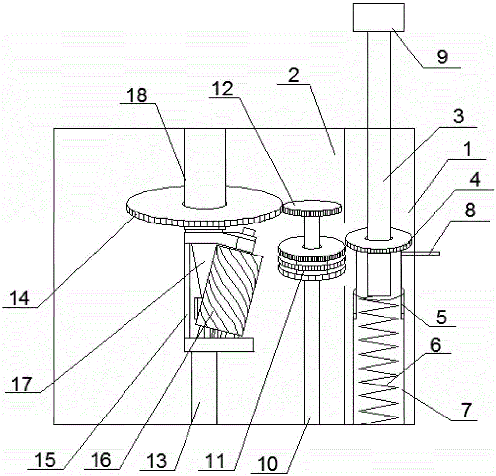
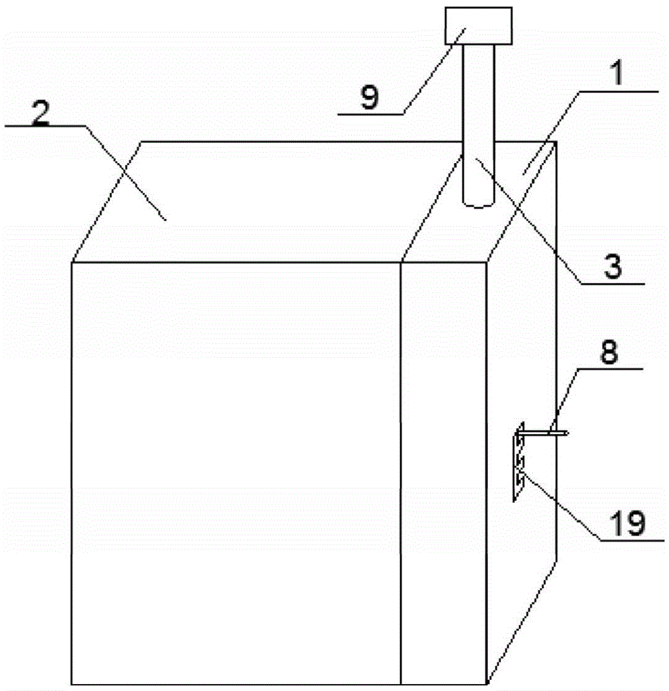
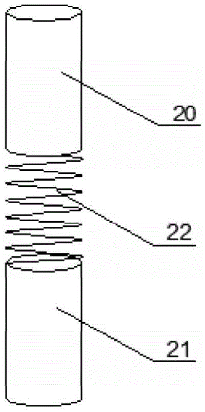
[0037] Such as Figure 1~4 As shown, the present invention provides a push-type pencil sharpener, which includes:

[0038] The housing has a hollow cuboid structure, and a vertical partition is provided in the middle of the housing, and the partition divides the housing into two spaces on the left and right, which are respectively the first space 1 and the second space 2, The middle part of the partition is provided with a first through hole, so that the first space 1 and the second space 2 are partly communicated, and the part of the housing located in the first space 1 and opp...


PUM


Abstract

The invention discloses a push type pencil sharpener. The push type pencil sharpener comprises a housing, a transmission mechanism, a driven mechanism, a cutting mechanism and a pencil inlet mechanism, wherein the housing comprises a first space and a second space which partly communicate with each other; an E-like second through hole is formed in the side surface of the housing, and the E-like second through hole comprises a vertical part and four horizontal parts which penetrate through the vertical part, so that four gear slots from top to bottom are formed; the transmission mechanism comprises a push rod, a first gear plate, a barrel sleeve and a compression spring; the driven mechanism comprises a rotary shaft, a second gear set and a fifth gear plate; the cutting mechanism comprises a fixed rod, a cutter holder and a milling cutter; the pencil inlet mechanism comprises a first part, a second part, an elastic element and a sixth gear plate. According to the push type pencil sharpener disclosed by the invention, energy can be stored through the compression spring, and the push rod drives the first gear plate to rotate by utilizing counter-acting force of the compression spring, so that the driven mechanism is further driven to rotate to drive the pencil inlet mechanism to rotate, and a pencil can be driven by the rotation of the pencil inlet mechanism to rotate relative to the cutting mechanism, so that the cutting work is completed, and therefore, the push type pencil sharpener has the advantages of being environmentally-friendly, energy-saving and quick.

Description

technical field [0001] The invention relates to a pencil sharpener. More particularly, the present invention relates to push-to-action pencil sharpeners. Background technique [0002] Pencils are tools for writing and note-taking purposes, and have accompanied the general public through many years. According to different uses of pencils, the requirements for the material of pencils are different. Different, for example, for softer wood, the cutting force requirement is lower, and for stronger wood, the required cutting force is greater. The pencil sharpeners currently used for sharpening pencils are divided into hand-operated and electric. The hand-operated pencil sharpener generally drives the cutting mechanism to rotate around the pencil by operating the manual handle, and finally completes the cutting work of the pencil. In the whole process, Although the cutting force can be controlled artificially to complete the cutting of different pencils, the user must rotate the ...

Claims


Application Information

Patent Timeline
Patent Type & Authority Applications(China)
IPC IPC(8): B43L23/02
CPCB43L23/02
Inventor 邓绍敏陈体勇古胜军
Owner 周庆芬
Why Eureka
Eureka Blog
Learn More