Connection rod type wire winding device

A wire winder and connecting rod type technology, applied in the field of connecting rod type wire winders, can solve the problems of short service life, inconvenient installation, complex structure of elastic clamping body, etc., and achieve the effect of convenient use and simple structure

Active Publication Date: 2016-05-04
RONGCHENG ZHONGYUAN ELECTRIC APPLIANCE
View PDF6 Cites 3 Cited by
  • Summary
  • Abstract
  • Description
  • Claims
  • Application Information

AI Technical Summary

Problems solved by technology

The clamping body and elastic clamping body disclosed above have complex structures, inconvenient installation, easy damage to the elastic clamping body, and short service life

Method used


Image

  • Connection rod type wire winding device
  • Connection rod type wire winding device
  • Connection rod type wire winding device

Examples


Embodiment Construction

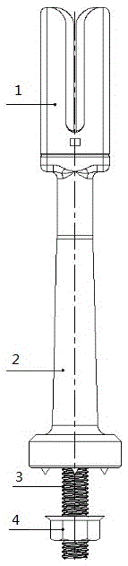
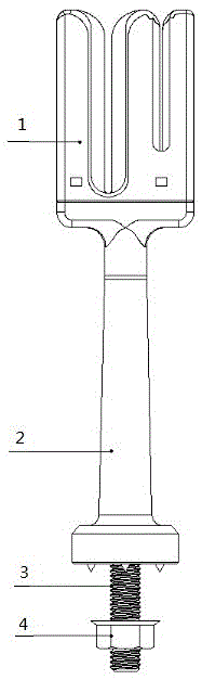
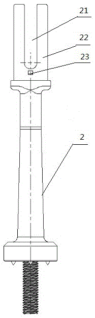
[0022] From figure 1 , figure 2 It can be seen from the figure that a connecting rod type wire winder includes a body 2. The lower part of the body 2 is provided with a screw 3 for installing it on the workbench. The screw 3 and the nut 4 cooperate to fix the body 2. effect. The body 2 of the present invention is the most basic structural part of the product, and its surface is required to be free of depressions, trachoma, air bubbles, and burrs, with a smooth surface and stable dimensions; the outer surface of the product must be treated by EDM discharge to achieve uniform appearance; Elastic rectangular support 22. The material of the screw 3 is A3, the extension length is 28 mm, and it is injected out of the mold together with the body.

[0023] The feature of the present invention is: the upper part of the body 2 is equipped with an elastic extrusion sleeve 1, the elastic extrusion sleeve 1 has an integral structure, and is fastened on each pillar on the upper part of ...


PUM


Abstract

The invention relates to a connection rod type wire winding device which comprises a body. The lower portion of the body is provided with a screw used for installing the body on a worktable. An elastic extrusion sleeve is installed on the upper portion of the body and is in an integral structure. The elastic extrusion sleeve is buckled to all supporting columns on the upper portion of the body. Extrusion pads with cavities are formed on the inner sides of U-shaped grooves among the supporting columns. Corresponding extrusion pads form U-shaped bayonets among the supporting columns. When the wire winding device is used for winding wires, cables are pressed into the U-shaped bayonets of the elastic extrusion sleeve, the extrusion pads are extruded and get close to the inner sides of the supporting columns, the clamped-in cables are tightly clamped and fixed through good elasticity of the elastic extrusion sleeve, the cables are distributed in order, and subsequent winding and binding actions are facilitated. The wire winding device is simple and reasonable in structure, convenient to operate and use, and wire arrangement, wire distribution and automatic clamping can be achieved. After winding and binding, people only need to lift up the cables, and the elastic extrusion sleeve cannot be damaged and can be repeatedly used.

Description

technical field [0001] The invention relates to the technical field of wire rods, in particular to a link type wire winder. Background technique [0002] In order to arrange the complicated cables in an orderly manner, the cables are usually arranged together using a cable distribution tool, and then manually wound and bundled. Existing cable distribution tools generally include a body, and two baffles are symmetrically arranged on the tiger's mouth of the body. During operation, manually press the arranged free cable, the free cable enters the U-shaped tiger mouth under the two baffles, the baffle is reset, and the free cable is blocked in the U-shaped tiger mouth. Then the operator frees up his hands for the next step of winding and bundling. Since the existing cable distribution tool does not have a clamp function, the free cable is out of manual control after entering the U-shaped tiger's mouth, and sometimes it will scatter, presenting a messy state, which is not cond...

Claims


Application Information

Patent Timeline
Patent Type & Authority Applications(China)
IPC IPC(8): B65H75/28B65H75/18
CPCB65H75/18B65H75/285
Inventor 钱金玉金应基
Owner RONGCHENG ZHONGYUAN ELECTRIC APPLIANCE
Why Eureka
Try Eureka