Load transfer method for power distribution network

A load transfer and distribution network technology, applied in the direction of electrical components, circuit devices, AC network circuits, etc., can solve the problem of easy overloading of the recovery path, and achieve the guarantee of recovery range, maximum guarantee, and high reliability Effect

Active Publication Date: 2016-05-04
DONGFANG ELECTRONICS
View PDF3 Cites 8 Cited by
  • Summary
  • Abstract
  • Description
  • Claims
  • Application Information

AI Technical Summary

Problems solved by technology

[0004] In order to solve the problem that the re-power path is easy to be overloaded, the present invention proposes a distribution network load transfer method

Method used


Image

  • Load transfer method for power distribution network

Examples


Embodiment Construction

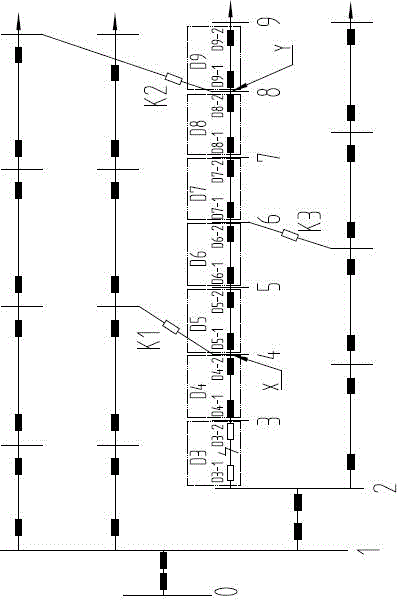
[0013] The technical solution of the present invention will be described in detail below in conjunction with the accompanying drawings. It should be understood that, for the convenience of operation, switches are usually installed at the upper and lower ends of the circuit between two nodes of the distribution network, and the upper end switch and the lower end switch are connected in series and are both A sub-switch of a group of switches, when it is necessary to disconnect the current circuit, only one of them needs to be disconnected. E.g, figure 1 Middle switch D4 actually includes sub-switches D4-1 and D4-2, and "disconnecting switch D4" means "disconnecting sub-switches D4-1 and, or D4-2 of switch D4, so that node 3 and node 4 The circuit between is disconnected". The rest of the switches are the same and will not be repeated here.

[0014] suppose figure 1 A failure of the switch D3 between node 2 and node 3 will result in power loss from node 3 to node 9, that is, n...


PUM


Abstract

The invention discloses a load transfer method for a power distribution network. The load transfer method comprises the following main steps: (1) determining an implementable switch set according to a non-fault power-losing region and the positions of backup switches; and (2) splitting and combining loads of the non-fault power-losing region according to the implementable switch set and margins of restoring paths on which the backup switches are located, and balancing the residual margins of the restored restoring paths. The method not only ensures the maximization of the restoring range, but also solves the problem that the restoring paths are easy to overload in the prior art, distributes the overload risk of the restoring paths into the restoring paths according to the margins, and has the advantage of high reliability.

Description

technical field [0001] The invention relates to a load transfer method of a distribution network, which belongs to the field of power distribution. Background technique [0002] There are a large number of section switches and tie switches in the distribution network, which make the distribution network have distinct variable structure characteristics. After a component fails, the downstream branch connected to the faulty component along the direction of the power flow will completely lose power. The power-off downstream branch is the non-fault power-off area. [0003] The power recovery scheme in the prior art is: according to the variable structure characteristics of the distribution network, after a branch circuit fails, close a backup switch to connect a power recovery path to restore power to the loads in the non-fault outage area, that is, "Break one into one". Due to the variable structure characteristics of the distribution network, there is no unique path to resto...

Claims


Application Information

Patent Timeline
Patent Type & Authority Applications(China)
IPC IPC(8): H02J3/00
CPCH02J3/0073
Inventor 潘凯岩谭大帅邓颖奇靳力林培明徐刚
Owner DONGFANG ELECTRONICS
Why Eureka
Try Eureka