A shield structure used between two smart cards

A shielding structure, smart card technology, applied in the fields of magnetic/electric field shielding, coatings, electrical components, etc., can solve problems such as non-normal use, mutual interference of electromagnetic fields, and inability to recognize card readers, saving time and improving reading efficiency. , the effect of shielding the mutual interference of electromagnetic fields

Active Publication Date: 2018-09-07
舟山安特佳智能科技有限公司
View PDF4 Cites 0 Cited by
  • Summary
  • Abstract
  • Description
  • Claims
  • Application Information

AI Technical Summary

Problems solved by technology

But the ensuing annoyance is that stacked smart cards usually cannot be used at the same time, that is, a card reader with a specific function cannot recognize the stacked smart cards
This is because the coupling elements in the two smart cards are triggered at the same time, and the electromagnetic fields of the two smart cards interfere with each other, causing the card reader to fail to recognize
Therefore, no matter whether the smart card to be used faces the corresponding card reader or not, as long as there are other stacked smart cards, they cannot be used normally and must be taken out for use separately.
[0005] Therefore, it is necessary to develop a product that can overcome the problem of electromagnetic field interference between the two stacked smart cards during the data reading process, and does not need to be taken out and used separately

Method used


Image

  • A shield structure used between two smart cards
  • A shield structure used between two smart cards
  • A shield structure used between two smart cards

Examples


Embodiment 1

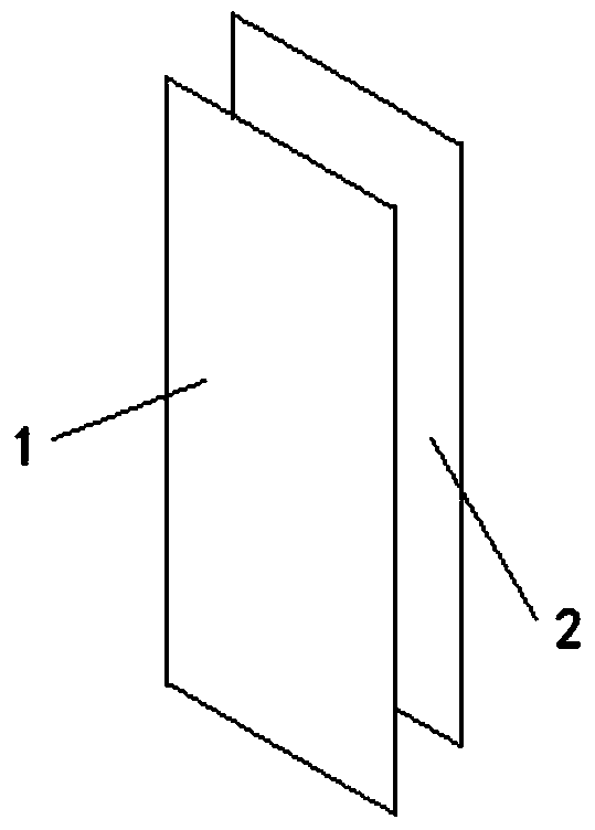
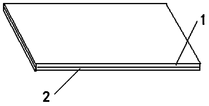
[0030] See attached figure 1 And attached figure 2 , the shielding structure used between two smart cards of the present invention includes a ferrite layer 1 and a conductor layer 2 . Both the ferrite layer 1 and the conductor layer 2 are thin plate or foil layer structures.

[0031] The ferrite layer 1 can be produced by known technical means, such as sputtering and deposition (gas phase or liquid phase), preferably by powder pressing and sintering. The ferrite layer 1 can also be replaced by other material layers with excellent magnetic permeability.

[0032] The conductor layer 2 can be made of a metal with excellent electrical conductivity, made of a thin plate or foil layer structure and physically stacked on the ferrite layer 1, or preferably attached to the ferrite layer 1 by deposition or plating, and ferrite layer 2 The body layer 1 becomes a layered one-piece structure.

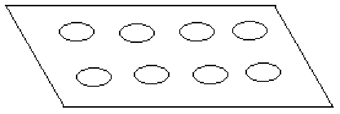
[0033] See attached image 3 And attached Figure 4 , the conductor layer 2 in the presen...

Embodiment 2

[0038] See attached Image 6 , the shielding structure applied between two smart cards of the present invention includes two layers of ferrite layers 1 and one layer of conductor layer 2, wherein the conductor layer 2 is placed between the two layers of ferrite layers 1 to form a sandwich structure Or called a sandwich structure. The three can be stacked or integrated.

[0039] Other descriptions about the ferrite layer 1 and the conductor layer 2 in the second embodiment are the same as those in the first embodiment, and will not be repeated here.

[0040] Specific application examples:

[0041] Such as Figure 7 As shown, the structure of Embodiment 1 of the present invention is preferably applied to the card holder 3 (also called a card sleeve, etc.). The tray 3 is usually made of plastic. The card tray 3 has a double-sided slot structure, and two smart cards can be respectively inserted into the two sides at the same time.

[0042] Wherein, the structure of the first...


PUM

PropertyMeasurementUnit
thicknessaaaaaaaaaa
thicknessaaaaaaaaaa
thicknessaaaaaaaaaa

Abstract

The present invention provides a shielding structure between two intelligent cards. The shielding structure comprises a conductor layer and at least one ferrite layer. The shielding structure arranged between two intelligent cards is able to effectively shield the mutual interference of an electromagnetic field between the two intelligent cards in the process of reading data so that the two stacking intelligent cards can be used with no need for individually removing. The shielding structure is able to improve the reading efficiency of stacking intelligent card so as to bring motion convenience for card holder and greatly save time, and is worthy of vigorous promotion and usage.

Description

technical field [0001] The invention belongs to the technical field of electromagnetic shielding and relates to a shielding structure used between two smart cards. Background technique [0002] Smart card technology is very mature and has a wide range of applications, generally including but not limited to second-generation ID cards, bus cards, employee cards, access control cards, electronic tags, etc. [0003] Existing smart cards typically use radio frequency identification (RFID) technology for data reading. Data transmission between the card reader and the smart card is carried out through a modulated electromagnetic field of a specific frequency. There are two ways of reading, active and passive. Actively read smart cards generally have their own power supply and can actively emit electromagnetic waves. The passively read smart card does not have a power supply, and the built-in coupling element obtains the energy of the electromagnetic wave emitted by the card read...

Claims


Application Information

Patent Timeline
Patent Type & Authority Patents(China)
IPC IPC(8): H05K9/00B32B9/04B32B15/09B32B3/24B32B3/12B32B7/12B32B7/08
CPCB32B3/12B32B3/266B32B7/08B32B7/12B32B9/041B32B9/045B32B15/09B32B2250/40B32B2255/06B32B2255/20B32B2307/202B32B2307/212H05K9/0081
Inventor 高特傅继奋高永立胡华炜王雷
Owner 舟山安特佳智能科技有限公司
Why Eureka
Try Eureka