Shielding structure between two intelligent cards
A shielding structure and smart card technology, applied in the direction of magnetic/electric field shielding, coating, electrical components, etc., can solve problems such as abnormal use, mutual interference of electromagnetic fields, and unrecognizable card readers, so as to save time and shield the interaction of electromagnetic fields Interference, the effect of improving reading efficiency
- Summary
- Abstract
- Description
- Claims
- Application Information
AI Technical Summary
Problems solved by technology
Method used
Image
Examples
Embodiment 1
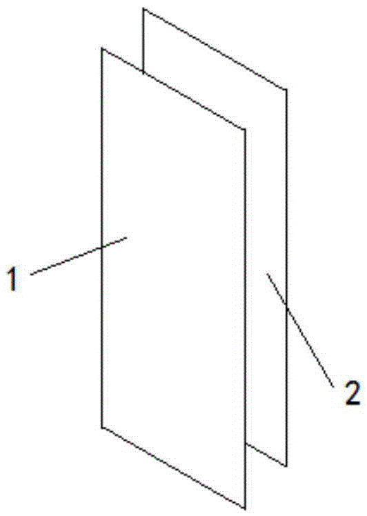
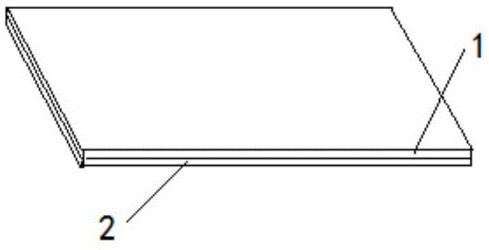
[0030] See attached figure 1 And attached figure 2 , the shielding structure used between two smart cards of the present invention includes a ferrite layer 1 and a conductor layer 2 . Both the ferrite layer 1 and the conductor layer 2 are thin plate or foil layer structures.
[0031] The ferrite layer 1 can be produced by known technical means, such as sputtering and deposition (gas phase or liquid phase), preferably by powder pressing and sintering. The ferrite layer 1 can also be replaced by other material layers with excellent magnetic permeability.
[0032] The conductor layer 2 can be made of a metal with excellent electrical conductivity, made of a thin plate or foil layer structure and physically stacked on the ferrite layer 1, or preferably attached to the ferrite layer 1 by deposition or plating, and ferrite layer 2 The body layer 1 becomes a layered one-piece structure.
[0033] See attached image 3 And attached Figure 4 , the conductor layer 2 in the presen...
Embodiment 2
[0038] See attached Figure 6 , the shielding structure applied between two smart cards of the present invention includes two layers of ferrite layers 1 and one layer of conductor layer 2, wherein the conductor layer 2 is placed between the two layers of ferrite layers 1 to form a sandwich structure Or called a sandwich structure. The three can be stacked or integrated.
[0039] Other descriptions about the ferrite layer 1 and the conductor layer 2 in the second embodiment are the same as those in the first embodiment, and will not be repeated here.
[0040] Specific application examples:
[0041] Such as Figure 7 As shown, the structure of Embodiment 1 of the present invention is preferably applied to the card holder 3 (also called a card sleeve, etc.). The tray 3 is usually made of plastic. The card tray 3 has a double-sided slot structure, and two smart cards can be respectively inserted into the two sides at the same time.
[0042] Wherein, the structure of the firs...
PUM
| Property | Measurement | Unit |
|---|---|---|
| thickness | aaaaa | aaaaa |
| thickness | aaaaa | aaaaa |
| thickness | aaaaa | aaaaa |
Abstract
Description
Claims
Application Information
 - R&D
- Intellectual Property
- Life Sciences
- Materials
- Tech Scout
- Unparalleled Data Quality
- Higher Quality Content
- 60% Fewer Hallucinations
Browse by: Latest US Patents, China's latest patents, Technical Efficacy Thesaurus, Application Domain, Technology Topic, Popular Technical Reports.
© 2025 PatSnap. All rights reserved.Legal|Privacy policy|Modern Slavery Act Transparency Statement|Sitemap|About US| Contact US: help@patsnap.com


