Switching signal interface circuit based on double photoelectric isolation

A technology for optoelectronic isolation circuits and switching signals, which is applied to electrical components, output power conversion devices, etc., and can solve problems such as strong electromagnetic interference, inability to separate control circuits and power circuits from a long distance, and inability to isolate power circuits.

Inactive Publication Date: 2012-09-19
ZHEJIANG UNIV
View PDF0 Cites 0 Cited by
  • Summary
  • Abstract
  • Description
  • Claims
  • Application Information

AI Technical Summary

Problems solved by technology

Among them, optical fiber isolation is mainly used in high-voltage and high-power power electronic converters, which can completely cut off the interference of power circuits on control circuits during signal transmission, but the cost of optical fiber isolation is relatively high
The traditional optocoupler isolation method cannot achieve long-distance isolation, and the control circuit and power circuit must be close to each other
In the power circuit, the voltage and current of the power semiconductor device change rapidly during the switching process, resulting in strong electromagnetic interference, which may have a great impact on the nearby weak current control circuit
This is reflected in the following aspects: (1) In high-power power electronic converters, the control circuit and the power circuit are required to have a long enough distance, but the traditional optocoupler isolation method still cannot separate the control circuit from the power circuit at a long distance. (2) There is still direct capacitive coupling between the primary and secondary sides of the optocoupler circuit, which cannot isolate the influence of the power circuit on the control circuit, and the interference signal in the power circuit will pass through the coupling capacitance between the primary and secondary sides of the optocoupler circuit (3) The sensor circuit on the high-voltage side will lead the high-voltage circuit interference signal to the low-voltage side circuit (similarly, the low-voltage side circuit may also interfere with the sensor circuit on the high-voltage side)

Method used


Image

  • Switching signal interface circuit based on double photoelectric isolation
  • Switching signal interface circuit based on double photoelectric isolation
  • Switching signal interface circuit based on double photoelectric isolation

Examples


Embodiment Construction

[0028] The specific implementation manners of the present invention will be explained below in conjunction with the accompanying drawings.

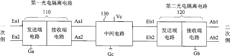
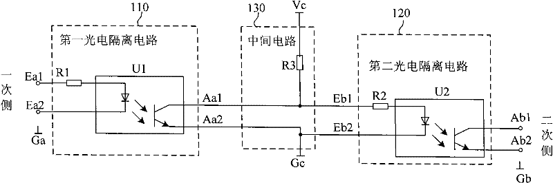
[0029] A preferred embodiment of the present invention is as image 3 As shown, it includes the first photoelectric isolation circuit 110, the intermediate circuit 130 and the second photoelectric isolation circuit 120, the reference ground Ga of the primary side switching signal, the reference ground Gb of the secondary side switching signal, the reference ground Gc of the intermediate circuit and the power supply of the intermediate circuit Vc; There is usually no electrical connection between the reference grounds Ga, Gb, and Gc of the three-part circuit, but sometimes to simplify the circuit, the reference ground of the intermediate circuit can be connected with the reference ground of the primary side switch signal and the reference ground of the secondary side switch signal The ground on one side is electrically connected (usually it...


PUM


Abstract

The invention relates to the technique of switching signal transmission in power electronic converters, aiming at providing a switching signal interface circuit based on double photoelectric isolation. The interface circuit comprises two photoelectric isolating circuits and an intermediate circuit; the first photoelectric isolating circuit receives a primary side switching signal and outputs a first intermediate switching signal according to the primary side switching signal; the intermediate circuit receives the first intermediate switching signal and outputs a second intermediate switching signal according to the first intermediate switching signal; and the second photoelectric isolating circuit receives the second intermediate switching signal and outputs a secondary side switching signal according to the second intermediate switching signal. The invention is applicable for the signal transmission of the switching signal with reliable electric isolation and interference shielding in the power electronic converters of relatively higher voltage class or relatively higher power class. The relatively long-distance isolation transmission can be achieved by the intermediate circuit, the influence of potential variation between high-voltage and low-voltage circuits on signal transmission is obviously inhibited as the potential of the intermediate circuit is relatively fixed; and one side of a sensitive control circuit can be far from high voltage.

Description

technical field [0001] The invention relates to a switching signal transmission technology in a power electronic converter, in particular to a switching signal interface circuit based on double photoelectric isolation. Background technique [0002] In recent years, power electronic converters have been widely used. The power electronic converter controls the on and off of the semiconductor devices in the power circuit through the weak current switch signal to realize power conversion, and at the same time the state switch signal in the power circuit is fed back to the control circuit. The so-called switch signal is a signal type different from the analog signal, which can be represented by two states of the circuit, such as two states of on and off, and two states of high level and low level. In power electronic circuits, switching signals are often used for drive control of switches such as power semiconductors and feedback of circuit status information. The control circu...

Claims


Application Information

Patent Timeline
Patent Type & Authority Patents(China)
IPC IPC(8): H02M1/44
Inventor 姚文熙吕征宇
Owner ZHEJIANG UNIV
Why Eureka
Try Eureka