
Component mounting apparatus

A technology for installing devices and components, applied in the direction of electrical components, electrical components, etc.

Active Publication Date: 2016-05-04
PANASONIC INTPROP MANAGEMENT CO LTD
View PDF10 Cites 9 Cited by
  • Summary
  • Abstract
  • Description
  • Claims
  • Application Information

AI Technical Summary

Problems solved by technology

[0005] However, if the safety state of the operator can be ensured even when the trolley holding the parts feeder is detached from the side of the base, the assembly head on the detached trolley side can be operated.

Method used


Image

  • Component mounting apparatus
  • Component mounting apparatus
  • Component mounting apparatus

Examples


Embodiment Construction

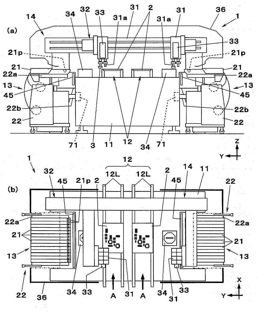
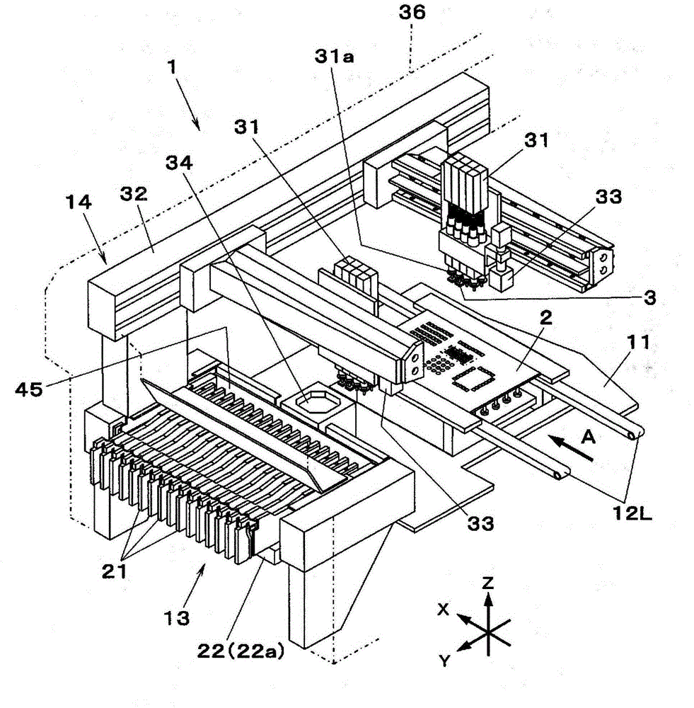
[0036] Hereinafter, embodiments of the present invention will be described with reference to the drawings. figure 1 (a), (b) and figure 2 The shown component mounting apparatus 1 represents one embodiment of the present invention. The component mounting apparatus 1 includes a substrate transport unit 12 , a component supply unit 13 , and a component mounting unit 14 on a base 11 , and repeatedly performs an operation of mounting a component 3 on a substrate 2 . Here, for convenience of description, the conveying direction in which the substrate conveying unit 12 conveys the substrate 2 ( figure 1 (b) and figure 2 The arrow A) shown in , is the X-axis direction (the left-right direction as viewed from the operator), and the horizontal in-plane direction (the front-rear direction as viewed from the operator) perpendicular to the X-axis direction is the Y-axis direction. In addition, let the up-down direction be a Z-axis direction.

[0037] exist figure 1 (a), (b) and fi...


PUM


Abstract

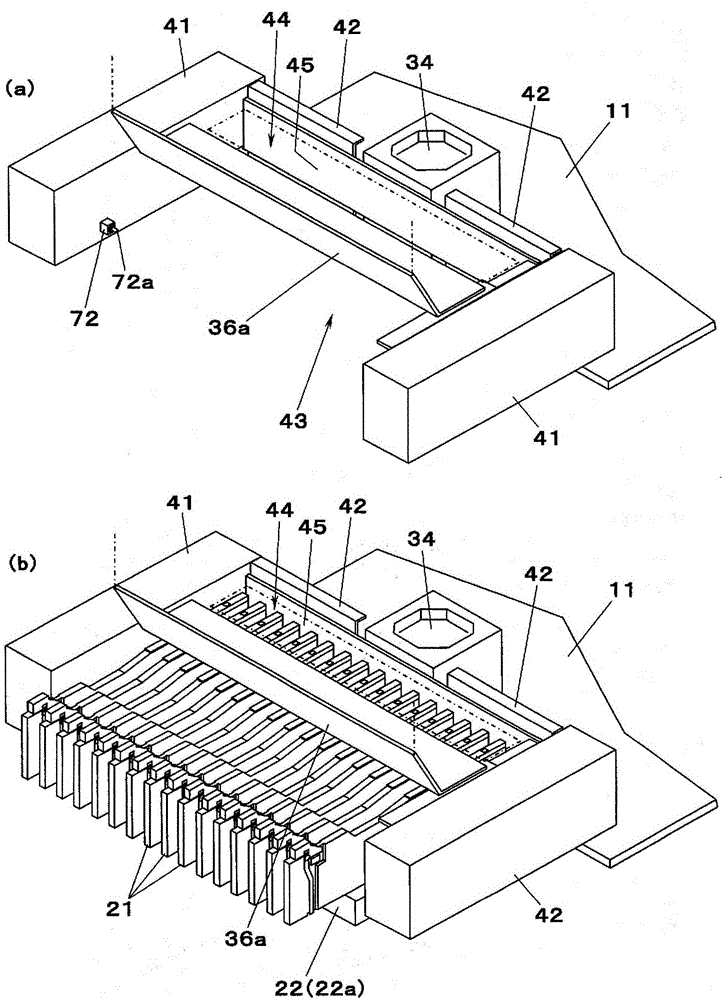
The objective of the invention is to provide a component mounting apparatus which can ensure the safety of an operator and keep motion of a mounting head in the case of disengagement of a carriage holding a part feeder from a base.The component mounting apparatus (1)includes a carriage (22) that holds a part feeder (21) for supplying a component (3) in a state of being attached to a base and attaches the part feeder to the base (11) in a state of being coupled to the base; a mounting head (31) that mounts the component to a substrate (2) after the component is taken out of the part feeder (21) held by the carriage coupled to the base through an opening (44) formed between the base and a cover member (36) formed so as to cover an upward side of the base; and a shutter (45) moved from an opened position in which the opening is opened to a closed position in which the opening is closed when the carriage is separated from the base.

Description

technical field [0001] The present invention relates to a component mounting device for mounting electronic components on a substrate. Background technique [0002] The component mounting apparatus includes: a parts feeder that supplies the components in a state mounted on the base; and a mounting head that takes out the components from the parts feeder mounted on the base and mounts them on the board. The component feeder is held on a trolley that can be freely coupled to and detached from the base, and the component feeder can be attached to the base by coupling the trolley to the base. An opening is formed between the base and a cover member provided to cover the base, and the mounting head passes through the opening to take out components from the component feeder held by the trolley. [0003] In such a component mounting device, when the cart is detached from the base, the cavity formed at the end of the base is exposed. The cavity leads to the movable area of ​​the a...

Claims


Application Information

Patent Timeline
Patent Type & Authority Applications(China)
IPC IPC(8): H05K13/04
CPCH05K13/0888H05K13/0417
Inventor 门田昌三石谷泰行远藤忠士浜知朗永冶利彦冈村浩志藤原弘之中岛诚
Owner PANASONIC INTPROP MANAGEMENT CO LTD
Learn More