Rack for ducted propeller assembly

A ducted propeller and propeller technology, which can be applied to workbenches, workpiece clamping devices, manufacturing tools, etc., can solve the problems of inability to realize the assembly of ducted propellers and difficulty in operation.

Active Publication Date: 2016-05-11
中国船舶重工集团公司第七〇二研究所
View PDF5 Cites 2 Cited by
  • Summary
  • Abstract
  • Description
  • Claims
  • Application Information

AI Technical Summary

Problems solved by technology

The assembly of ordinary propellers is to fix the propeller hub on the propeller shaft, and then install the propeller blades on the propeller hub. However, when this method of assembling ordinary propellers is applied to the assembly of ducted propellers, there are the following technical problems: The diameter of the inlet of the duct is usually larger than the diameter of the outlet, and the propeller is installed in the duct near the outlet of the duct. Since the diameter of the propeller is larger than the diameter of the exit of the duct, and the gap between the inner wall of the duct and the tip of the propeller blade is very small, it is necessary to install the propeller in the duct. It is very difficult to install the propeller on the propeller hub, especially for the deceleration duct where the duct and guide vane mounting seat are integrally non-detachable. Above, the guide vane is fixedly connected to the inner wall of the duct, and the propeller is fixed on the propeller shaft, and is located on the side close to the outlet of the duct. It is almost impossible to assemble the ducted propeller according to the assembly method of the ordinary propeller.

Method used


Image

  • Rack for ducted propeller assembly
  • Rack for ducted propeller assembly
  • Rack for ducted propeller assembly

Examples


Embodiment Construction

[0024] The specific implementation manner of the present invention will be described below in conjunction with the accompanying drawings.

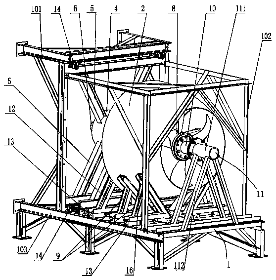
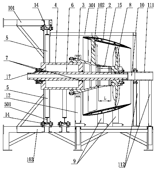
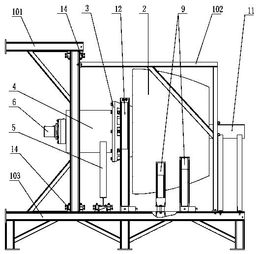
[0025] See figure 1 , figure 2 , image 3 , Figure 4 , the platform for assembling the ducted propeller of the present embodiment includes a mounting frame 1. In the ducted propeller to be assembled, the outer periphery of the duct 2 is fixedly supported on the mounting frame 1 through the support seat 9, and the outer periphery of the guide vane mounting seat 3 passes through the support seat. Two 12 are fixedly supported on the mounting frame 1, and one end of the guide vane mounting seat 3 is fixedly connected to the sleeve 4. In order to make the axial connection between the sleeve 4 and the guide vane mounting seat 3 more reliable, one end of the sleeve 4 can be extended Into the guide vane mounting seat 3, the sleeve 4 is arranged on the inlet side of the conduit 2, the sleeve 4 is fixedly supported on the mounting frame 1 throu...


PUM


Abstract

The invention discloses a rack for ducted propeller assembly. The rack comprises a mounting frame; in a ducted propeller, the outer periphery of a duct is fixedly supported on the mounting frame through support bases 1; the outer periphery of a guide blade mounting base is fixedly supported on the mounting frame through a support base 2; one end of the guide blade mounting base is fixedly connected with a sleeve; the sleeve is arranged on one side of an inlet near the duct, is fixedly supported on the mounting frame through a bracket, and sheaths a paddle shaft in a penetrating way; the paddle shaft is slidingly supported in the sleeve through slide bearings; a paddle hub of the propeller in the duct is fixedly mounted on the paddle shaft; an axial gap is left between the propeller and the guide blade mounting base; the shaft section of the paddle shaft positioned in the axial gap is coated with a transition section; one end of the transition section is detachably and fixedly connected with the guide blade mounting base; and a rotating gap is left between the other end of the transition section and the paddle hub of the propeller. The rack can quickly and accurately finish assembly of the ducted propeller.

Description

technical field [0001] The invention relates to the technical field of underwater propulsion devices, in particular to a ducted propeller, and in particular to a platform for assembling the ducted propeller. Background technique [0002] The ducted propeller is a widely used underwater propulsion device. It refers to adding a duct around the propeller. The duct can be fixed or rotated as a whole. Compared with ordinary propellers, due to the diversion of the duct, the propulsion can be improved. force. The assembly of ordinary propellers is to fix the propeller hub on the propeller shaft, and then install the propeller blades on the propeller hub. However, when this method of assembling ordinary propellers is applied to the assembly of ducted propellers, there are the following technical problems: The diameter of the inlet of the duct is usually larger than the diameter of the outlet, and the propeller is installed in the duct near the outlet of the duct. Since the diameter...

Claims


Application Information

Patent Timeline
Patent Type & Authority Applications(China)
IPC IPC(8): B25B11/02B25H1/10
CPCB25B11/02B25H1/10
Inventor 曹耀初孙红星吴健王森金周斌芮伟
Owner 中国船舶重工集团公司第七〇二研究所
Why Eureka
Try Eureka