
Aircraft flight direction control device

A technology of flight direction and control device, which is applied in the direction of aircraft transmission, aircraft power device, aircraft power transmission, etc., and can solve the problems of large power loss and small effective lift of small aircraft

Active Publication Date: 2018-04-13
杨海燕
View PDF4 Cites 0 Cited by
  • Summary
  • Abstract
  • Description
  • Claims
  • Application Information

AI Technical Summary

Problems solved by technology

It can be seen that the power loss of the above-mentioned small aircraft is relatively large, and the effective lift is small.

Method used

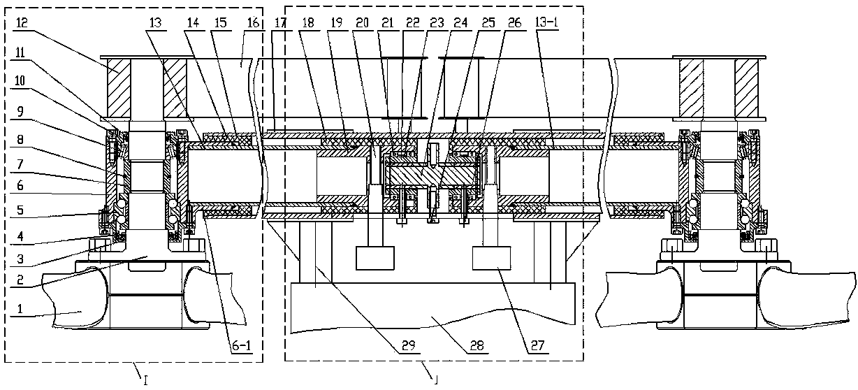
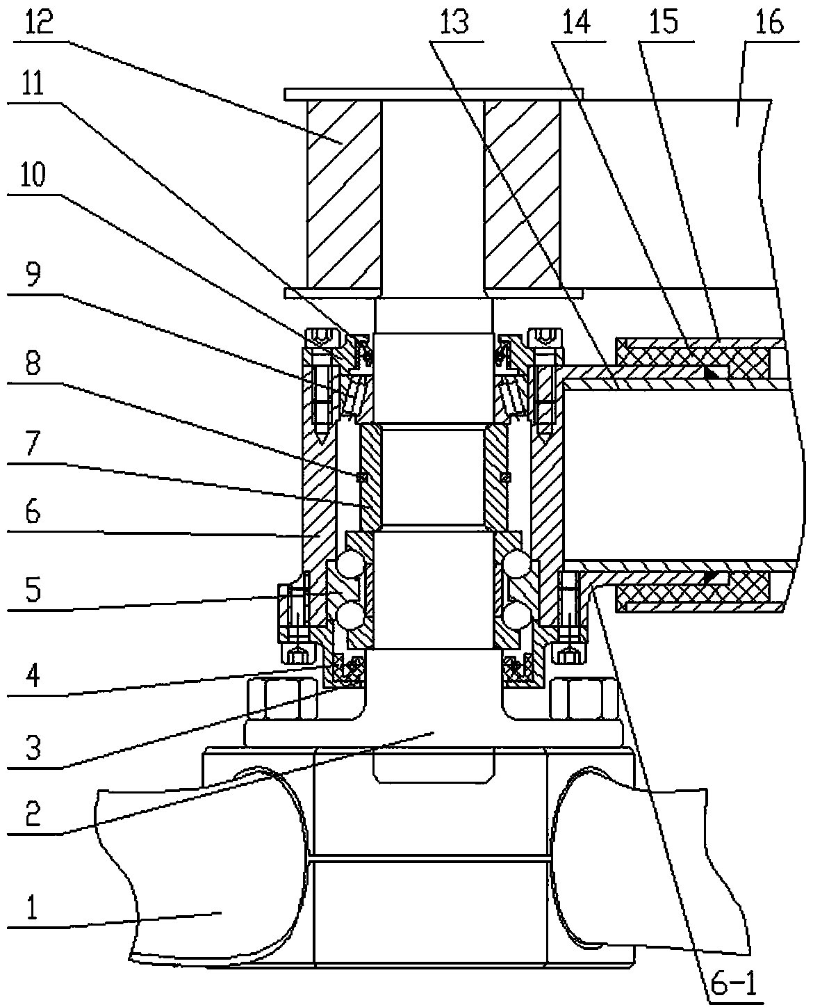
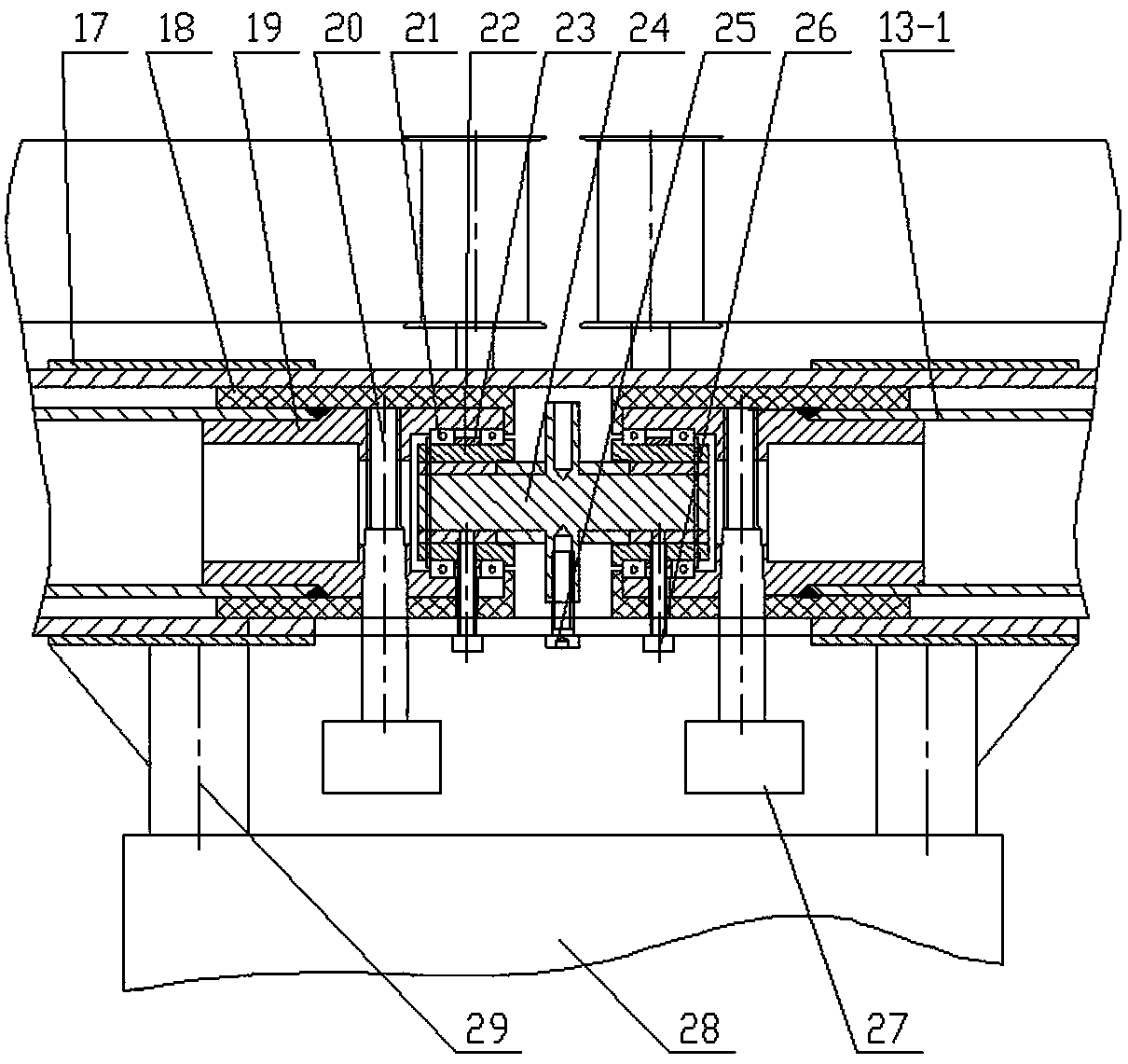

Image

  • Aircraft flight direction control device
  • Aircraft flight direction control device
  • Aircraft flight direction control device

Examples


Embodiment Construction

[0017] Such as figure 1 , figure 2 and image 3 As shown, the aircraft flight direction control device of the present invention includes a main beam 15 and two propellers 1 . The main beam 15 is a hollow tube, and an adjusting screw 24 is arranged in the middle of its inner cavity. Both ends of the adjusting screw 24 are processed with external threads and are screwed with nuts 22 , and the rotation directions of the two nuts 22 are opposite. Both ends of the adjusting screw 24 are provided with half-axis tubes, and the inner ends of the half-axis tubes are rotatably sleeved on the corresponding nuts 22 . Arc holes are processed on the lower wall of the main beam 15 corresponding to the two ends of the adjusting screw 24, and an electric cylinder 27 and a rotating arm 20 are arranged below the main beam 15 corresponding to the arc holes. The lower end of the rotating force arm 20 is connected, and the upper end of the rotating force arm 20 passes through the corresponding...


PUM


Abstract

The invention discloses a flight direction control device of an aircraft. The flight direction control device comprises a girder and two propellers. The flight direction control device is characterized in that the girder is a hollow circular tube, the middle of an inner cavity of the hollow circular tube is provided with an adjusting screw, and nuts are screwed to the two ends of the adjusting screws respectively; the two ends of the adjusting screw are provided with half shaft tubes respectively, and the inner end of each half shaft tube is rotatably arranged on the corresponding nut in a sleeved mode; the lower walls, corresponding to the two ends of the adjusting screw, of the girder are provided with arc holes, an electric cylinder and a rotating force arm are arranged below the positions, corresponding to the arc holes, of the girder, a stretching and contracting shaft of the electric cylinder is connected with the lower end of the rotating force arm, and the upper end of the rotating force arm is fixedly connected with the half shaft tubes; the outer ends of the two half shaft tubes are provided with bearing seats respectively, and the two bearing seats are internally provided with propeller shafts respectively; the upper ends of the two propeller shafts are provided with belt wheels, and a transmission belt is connected between the two belt wheels; the propellers are connected to the lower ends of the two propeller shafts. By means of the adjusting structure, the power loss of a small aircraft can be lowered, and effective lift force is improved; the flight direction control device is suitable for controlling the small aircraft in four directions.

Description

technical field [0001] The invention relates to a small aircraft. Specifically, it is a propeller pitch angle adjustment mechanism on a small aircraft that can take off and land under narrow and complex terrain conditions such as mountains or canyons. It is suitable for controlling the left, right, up and down directions of small aircraft. Background technique [0002] Chinese Patent No. ZL2013104235571 discloses a small aircraft that can take off and land on complex terrain. This small aircraft includes a main frame, two ducts, a lateral swing wing, a longitudinal swing wing, a direction control mechanism, an engine and a support. The axes of the ducts are parallel. There is a shaft seat in the center of the inner cavity of the duct, and there is a paddle shaft in the shaft seat, and the two are rotatably matched. A propeller is arranged at the upper end of the paddle shaft, and the outer walls of the two ducts are connected by a connecting frame. The main frame is conn...

Claims


Application Information

Patent Timeline
Patent Type & Authority Patents(China)
IPC IPC(8): B64C13/28
CPCB64C13/28
Inventor 杨国社
Owner 杨海燕
Learn More