Quick replacement device for furnace roller of thermal treatment furnace

A technology for heat treatment furnaces and furnace rolls, applied in heat treatment furnaces, heat treatment equipment, furnaces, etc., can solve problems such as long time for changing rolls, damage to refractory materials in the furnace, and heavy workload, and achieve simple installation, reduced labor intensity, and reduced The effect of small labor risks

Active Publication Date: 2016-05-11
LAIWU IRON & STEEL GRP
View PDF5 Cites 3 Cited by
  • Summary
  • Abstract
  • Description
  • Claims
  • Application Information

AI Technical Summary

Problems solved by technology

However, due to the compact structure of the heat treatment furnace and the small space, it is easy to cause damage and deformation of the refractory materials in the furnace during the process of replacing the furnace rollers, and the time for changing the rollers is long and the workload is heavy.

Method used


Image

  • Quick replacement device for furnace roller of thermal treatment furnace
  • Quick replacement device for furnace roller of thermal treatment furnace
  • Quick replacement device for furnace roller of thermal treatment furnace

Examples


Embodiment Construction

[0020] The technical solution of the present invention will be clearly and completely described below in conjunction with the accompanying drawings.

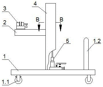
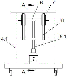
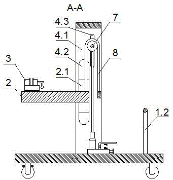
[0021] like figure 1 A heat treatment furnace roller quick replacement device is shown, including a clamping device, a moving guide device and a fixed guide device, such as figure 1 The clamping device shown includes a trolley 1 fixed with a gantry-shaped frame 4 and a disassembly platform 2 with a slider 2.1 fixed thereon. A vise 3 is fixed on the disassembly platform 2, and columns 4.1 on both sides of the gantry-type frame 4 are Both are provided with a vertical groove 4.2 adapted to the slider 2.1, and the slider 2.1 slides into the vertical groove 4.2; a hydraulic jack 5 is also fixed on the trolley 1, and the upper end of the ejector rod 5.1 of the hydraulic jack 5 is fixedly connected There is a cross bar 6, on which two sprockets 7 are connected through bearings, and chains 8 are meshed on the sprockets 7, one end of th...


PUM


Abstract

The invention discloses a quick replacement device for a furnace roller of a thermal treatment furnace. The quick replacement device comprises a clamping device, a mobile guide device and a fixed guide device. The clamping device comprises a trolley and a demounting platform fixedly provided with sliding blocks, and a gantry framework is fixed to the trolley. A bench clamp is fixed to the demounting platform. The quick replacement device further comprises a hydraulic jack fixed to the trolley; the hydraulic jack is connected with the demounting platform through a chain and a chain wheel. The mobile guide device comprises a first U-type bolt and a first cross beam in threaded connection with the first U-type bolt. The two ends of the first cross beam are in rolling connection with furnace rollers arranged on two sides of a furnace roller needing to be replaced in an adjacent mode correspondingly. The fixed guide device comprises a second U-type bolt and a second cross beam in threaded connection with the second U-type bolt. The arc section of the second U-type bolt is provided with at least one second idler wheel. The two ends of the second cross beam are fixedly provided with second supporting frames with magnets.

Description

technical field [0001] The invention relates to the field of mechanical equipment, in particular to a rapid replacement device for furnace rollers of a heat treatment furnace. Background technique [0002] The heat treatment furnace of wide and thick plate line is the heat treatment equipment of steel plate, which is the main equipment to improve the product performance. It has the advantages of compact structure, low energy consumption, precise temperature control and high production efficiency. The inside of the heat treatment furnace is conveyed by roller table as steel plate in the furnace Equipment, the furnace rollers in the furnace operate at high temperature for a long time, and nodules or bulges will occur on the surface of the furnace rollers. In order to avoid scratching the surface of the steel plate, it is necessary to replace the bulged or noduled furnace rollers. However, due to the compact structure of the heat treatment furnace and the small space, it is eas...

Claims


Application Information

Patent Timeline
Patent Type & Authority Applications(China)
IPC IPC(8): C21D9/00
CPCC21D9/0006C21D9/0081
Inventor 刘明孟祥瑞王化胜孙时健阴法亮吕凤郭承勇陈建磊
Owner LAIWU IRON & STEEL GRP
Why Eureka
Try Eureka