Semi-automatic clutch device

A clutch device, semi-automatic technology, applied in the direction of sliding coupling, mechanical equipment, coupling, etc., can solve the problem that the host equipment is not applicable, does not have overload protection function, and the coupling cannot automatically disconnect the main and driven shafts and other problems, to achieve the effect of compact structure, safe and reliable operation, and extended service life

Active Publication Date: 2018-06-29
TRUKING TECH LTD
View PDF5 Cites 0 Cited by
  • Summary
  • Abstract
  • Description
  • Claims
  • Application Information

AI Technical Summary

Problems solved by technology

Couplings are widely used as a conventional transmission mechanism between the main and driven shafts, but the couplings cannot automatically disconnect the connection between the main and driven shafts. They do not have overload protection functions and are not suitable for automatic control. Stopped host device

Method used


Image

  • Semi-automatic clutch device
  • Semi-automatic clutch device
  • Semi-automatic clutch device

Examples


Embodiment Construction

[0018] The present invention will be further described in detail below in conjunction with the accompanying drawings and specific embodiments.

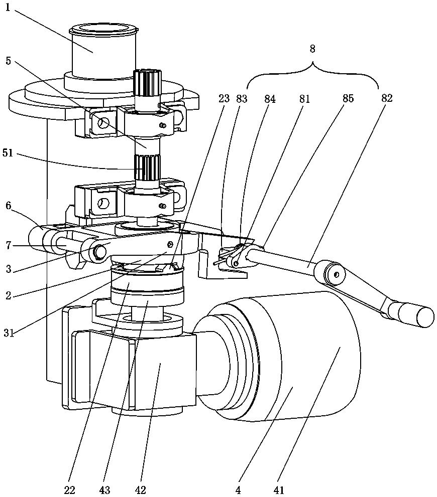
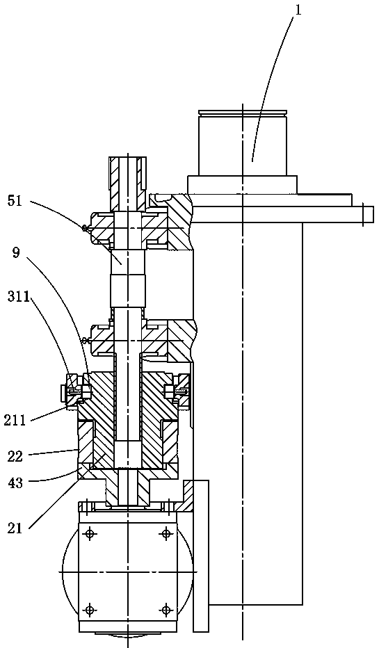
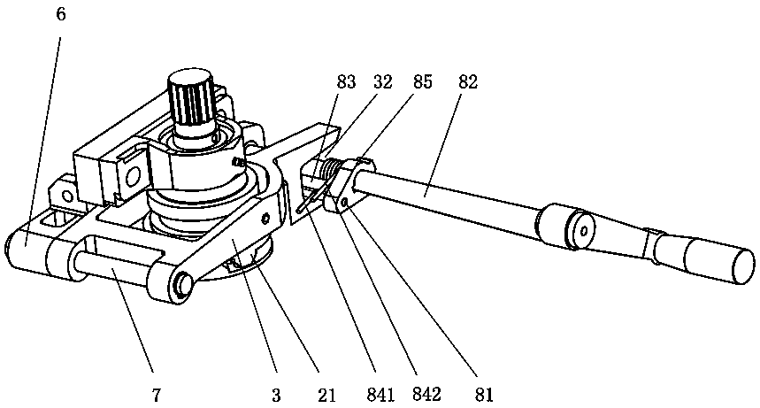
[0019] Figure 1 to Figure 3 An embodiment of the semi-automatic clutch device of the present invention is shown, the semi-automatic clutch device includes a main shaft seat 1, a clutch 2 and a connecting rod 3, the clutch 2 includes a clutch upper plate 21 and a clutch lower plate 22 meshing with each other, and the clutch lower plate 22 It is connected with the power part 4, the clutch upper plate 21 is connected with the driven part 5, the bearing seat 6 is fixed on the main shaft seat 1, the head end of the connecting rod 3 is hinged with the bearing seat 6 and the middle part is fixedly connected with the clutch upper plate 21, and the connecting rod 3 The tail end is provided with a locking assembly 8, which locks the upper clutch plate 21 and the lower clutch plate 22 by pressing the connecting rod 3. When the driven part 5 is ...


PUM


Abstract

The invention discloses a semi-automatic clutch device, which comprises a main shaft seat, a clutch and a connecting rod. The head end of the rod is hinged with the bearing seat and the middle part is fixedly connected with the clutch upper plate. The end of the connecting rod is equipped with a locking assembly, which locks the clutch upper plate and the clutch lower plate by pressing the connecting rod. When the driven part is overloaded When the clutch upper plate and the clutch lower plate overcome the pressing force of the locking assembly and separate, the present invention has the advantages of prolonging the service life of the power components, compact structure, simple operation, safety and reliability.

Description

technical field [0001] The invention relates to the technical field of transmission mechanisms, in particular to a semi-automatic clutch device. Background technique [0002] In the field of medical and food packaging machinery, capping machines and other types of equipment require transmission mechanisms to automatically disconnect the connection between the host and the drive motor when the host is overloaded, so as to avoid overloading the motor when the host is overloaded and affect the service life of the motor. Couplings are widely used as a conventional transmission mechanism between the main and driven shafts, but the couplings cannot automatically disconnect the connection between the main and driven shafts. They do not have overload protection functions and are not suitable for automatic control. Stopped host device. Contents of the invention [0003] The technical problem to be solved by the present invention is to overcome the deficiencies of the prior art and...

Claims


Application Information

Patent Timeline
Patent Type & Authority Patents(China)
IPC IPC(8): F16D7/00
Inventor 刘建勇
Owner TRUKING TECH LTD
Why Eureka
Try Eureka