Method of adjusting working frequency of antenna radiation body and corresponding mobile terminal

A technology of antenna radiator and working frequency, which is applied in the field of wireless communication, can solve the problems of poor performance of antenna radiator, inability to fully meet the needs of mobile terminals, and increase in number

Inactive Publication Date: 2016-05-11
SHENZHEN EASTAEON TECH
View PDF3 Cites 3 Cited by
  • Summary
  • Abstract
  • Description
  • Claims
  • Application Information

AI Technical Summary

Problems solved by technology

[0003] The antenna radiator of the mobile terminal in the industry is fixed on a conventional structural member (bracket) by fixing a metal material of a certain shape. The antenna radiator and the bracket radiate energy at a fixed frequency as a whole. The excellent radiation performance of the mobile terminal and It depends entirely on the performance of the antenna engineer to debug the antenna radiator on the existing structure, resulting in poor performance of the antenna radiator of some models of mobile terminals
On the other hand, due to the increasing size of mobile terminal screens and batteries, the thickness of the whole machine is gradually thinning, leaving a very poor environment for the antenna space, and with the development of new technologies, the number of radio frequency bands supported by mobile terminals is increasing. As more and more antenna radiators need to support a sharp increase in the frequency range, in this case, the existing antenna radiator technology in the industry has become increasingly unable to fully meet the needs of mobile terminals

Method used


Image

  • Method of adjusting working frequency of antenna radiation body and corresponding mobile terminal
  • Method of adjusting working frequency of antenna radiation body and corresponding mobile terminal
  • Method of adjusting working frequency of antenna radiation body and corresponding mobile terminal

Examples


Embodiment Construction

[0032] The present invention provides a method for adjusting the working frequency of the antenna radiator and the corresponding mobile terminal and the electronic product. In order to make those skilled in the art understand the solution of the present invention more clearly, and make the above-mentioned purpose, features, and The beneficial effect can be more clear and easy to understand, the following is combined with the attached Figure 1~9 The present invention will be further described in detail with specific embodiments.

[0033] The present invention also provides a method for adjusting the working frequency of the antenna radiator and the corresponding mobile terminal, the following will be combined with the attached Figure 1~9 The present invention will be further described in detail with specific embodiments.

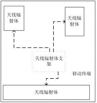
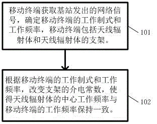
[0034] A method for adjusting the operating frequency of an antenna radiator, comprising:

[0035] Step 101: The mobile terminal obtains the network sign...


PUM


Abstract

The invention provides a method of adjusting a working frequency of an antenna radiation body. The method comprises the following steps that A, a mobile terminal acquires a network signal emitted by a base station, a working form and a working frequency of the mobile terminal are determined, and the mobile terminal comprises the antenna radiation body and a support of the antenna radiation body; and B, according to the working form and the working frequency of the mobile terminal, a dielectric constant of the support is changed so that a center working frequency of the antenna radiation body maintains consistent with the working frequency of the mobile terminal. A material of the support comprises quantum paraelectrics and / or a multiferroic material. Through applying an electric field, a magnetic field or a force, the dielectric constant of the support is changed so that the working frequency of the antenna radiation body is changed and the working form and the working frequency of the antenna radiation body are adjusted. The mobile terminal can carry out working frequency adjusting on the antenna radiation body according to the needed working form and the working frequency and a needed frequency range can be supported. Correspondingly, the invention also provides the mobile terminal capable of adjusting the working frequency of the antenna radiation body.

Description

technical field [0001] The invention relates to the technical field of wireless communication, in particular to a method for adjusting the working frequency of an antenna radiator and a corresponding mobile terminal. Background technique [0002] With the promotion of the fourth-generation mobile communication technology business and the development and maturity of more advanced mobile technologies such as the fifth-generation mobile communication technology, mobile terminals need to support more and more communication systems, and the supported communication frequency bands are becoming wider and wider. , which will inevitably lead to increasing difficulty in designing antenna radiators for generating wireless communication signals. [0003] The antenna radiator of the mobile terminal in the industry is fixed on a conventional structural member (bracket) by fixing a metal material of a certain shape. The antenna radiator and the bracket radiate energy at a fixed frequency a...

Claims


Application Information

Patent Timeline
Patent Type & Authority Applications(China)
IPC IPC(8): H01Q1/12
Inventor 杜天波邢亮
Owner SHENZHEN EASTAEON TECH
Why Eureka
Try Eureka