
A kind of reconfigurable antenna and terminal equipment

A technology for reconfiguring antennas and coaxial feeders, applied in antennas, radiating elements, electrical components, etc., can solve problems such as noise and interference, and achieve the effect of narrow antenna bandwidth and increased complexity

Active Publication Date: 2019-08-02
YULONG COMPUTER TELECOMM SCI (SHENZHEN) CO LTD
View PDF1 Cites 0 Cited by
  • Summary
  • Abstract
  • Description
  • Claims
  • Application Information

AI Technical Summary

Problems solved by technology

It can solve the noise and interference problems caused by the introduction of active devices to adjust the frequency point of the antenna in the prior art

Method used


Image

  • A kind of reconfigurable antenna and terminal equipment
  • A kind of reconfigurable antenna and terminal equipment
  • A kind of reconfigurable antenna and terminal equipment

Examples


Embodiment Construction

[0026] The following will clearly and completely describe the technical solutions in the embodiments of the present invention with reference to the accompanying drawings in the embodiments of the present invention. Obviously, the described embodiments are only some, not all, embodiments of the present invention. Based on the embodiments of the present invention, all other embodiments obtained by persons of ordinary skill in the art without creative efforts fall within the protection scope of the present invention.

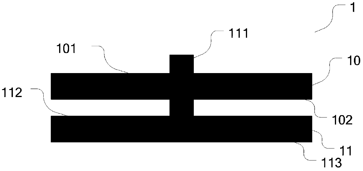
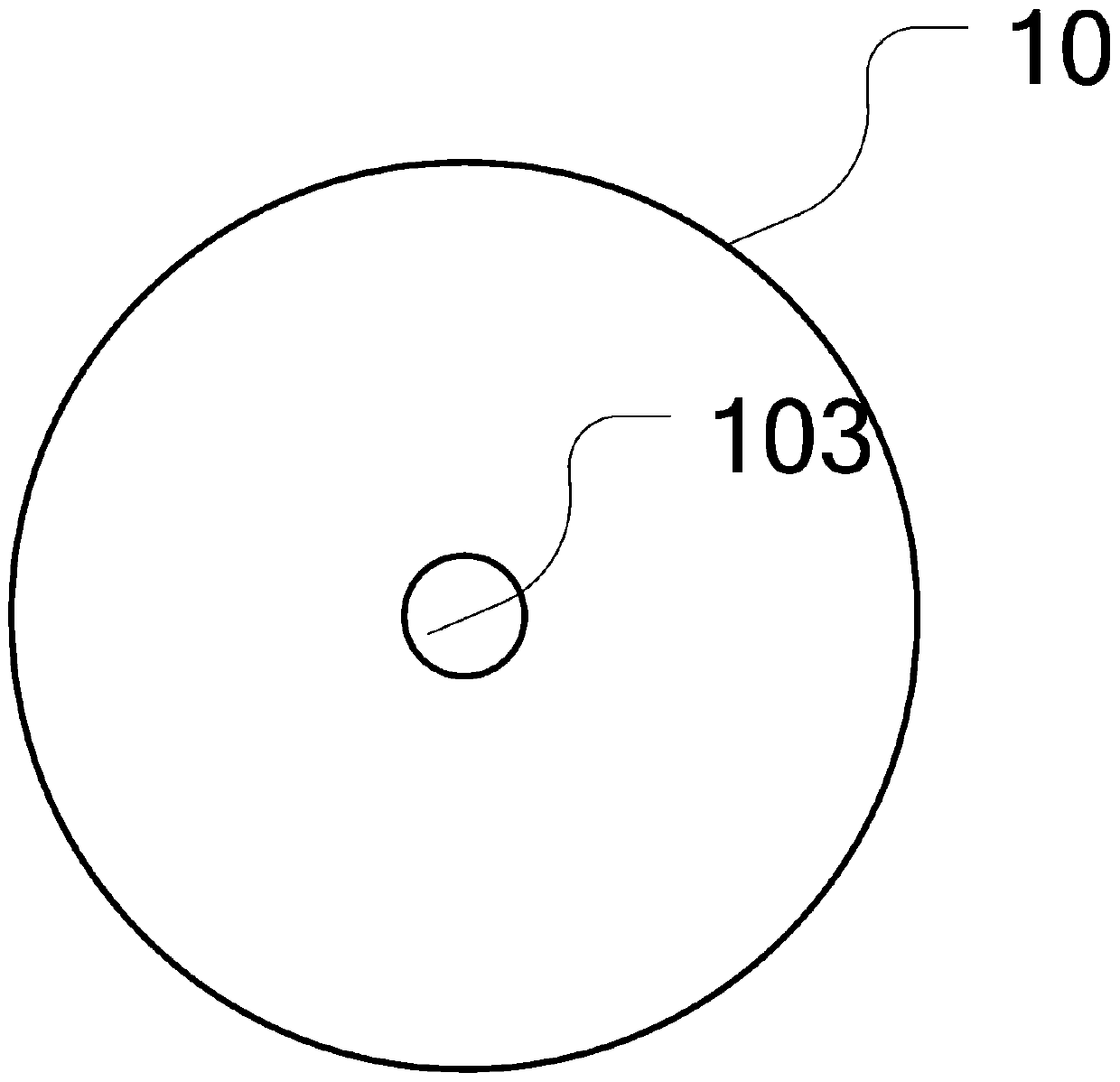
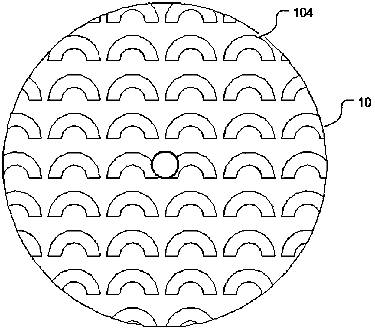
[0027] see Figure 1 to Figure 3b , is a structural diagram of a reconfigurable antenna provided by an embodiment of the present invention. In an embodiment of the present invention, the reconfigurable antenna includes a first circular dielectric substrate 11, a second circular dielectric substrate 10, a radiator 114, Coaxial feeder 116 and metal ground plate 117, wherein the first circular dielectric substrate 11, radiator 114, coaxial feeder 116 and metal ground ...


PUM


Abstract

An embodiment of the invention discloses a reconfigurable antenna. A radiator body is attached to the lower surface of a first circular dielectric substrate; a metal grounding plate is attached to the upper surface of the first circular dielectric substrate; a coaxial feeder line is arranged inside the first circular dielectric substrate; an inner conductor of the coaxial feeder line is electrically connected with the radiator body, and an outer conductor of the coaxial feeder line is electrically connected with the metal grounding plate; a plurality of metal patches are attached on the upper surface of a second circular dielectric substrate; the circle center of the upper surface of the first circular dielectric substrate is provided with a cylinder perpendicular to the first circular dielectric substrate; the circle center of the second circular dielectric substrate is provided with a run-through circular hole; the cylinder is inserted into the circular hole to enable the upper surface of the first circular dielectric substrate to be contacted with the lower surface of the second circular dielectric substrate. The embodiment of the invention also discloses a terminal device. According to the reconfigurable antenna and the terminal device, the frequency point of the reconfigurable antenna is adjusted in a passive manner, and the design difficulty of the antenna is reduced.

Description

technical field [0001] The present invention relates to the field of antennas, in particular to a reconfigurable antenna and terminal equipment. Background technique [0002] With the development of mobile communication technology, more stringent requirements are put forward for antennas of mobile terminals such as mobile phones. At present, when designing mobile phone antennas, if you want to design a communication main antenna that meets the requirements of 2G / 3G / 4G, you need the mobile phone main antenna to be able to cover at least 1880MHz-2650MHz. At present, the frequency band of the main antenna is not wide enough when many mobile phone antennas are designed. This defect can seriously affect the quality of communication. In this case, the emergence of reconfigurable frequency band can solve this problem well. When the antenna is working, the intelligent system senses the specific working frequency band at a specific time. Then the antenna automatically switches to...

Claims


Application Information

Patent Timeline
Patent Type & Authority Patents(China)
IPC IPC(8): H01Q1/38H01Q3/02
Inventor 韩崇志罗振宇李克
Owner YULONG COMPUTER TELECOMM SCI (SHENZHEN) CO LTD
Learn More