

Link control method and device
A link control and link information technology, applied in digital transmission systems, electrical components, transmission systems, etc., can solve problems such as bandwidth inconsistency, network traffic drop, switching unit congestion, etc., to ensure traffic levels, improve performance, The effect of solving local congestion and packet loss
- Summary
- Abstract
- Description
- Claims
- Application Information
AI Technical Summary
Problems solved by technology
Method used
Image

Examples
Embodiment 1
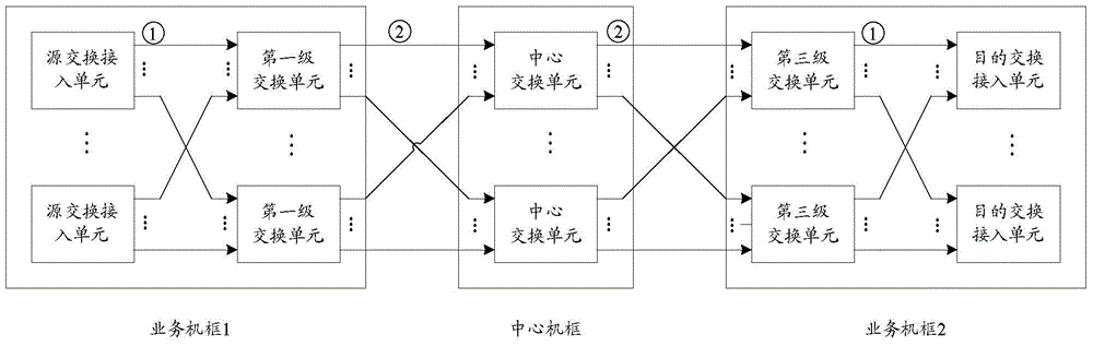
[0101] The embodiment of the present invention solves the problem of asymmetry between the second-level and third-level switching units through hierarchical processing. For the asymmetry of the third-level switching unit in the service frame, for each destination switching access unit, by sending unreachable information, ensure that the total input bandwidth of the input link of the current switching unit is less than or equal to its total output bandwidth For the asymmetry of the second-level switching unit of the central chassis, all service chassis are considered as a whole, and the access unit is switched for each purpose to ensure that each source service chassis The input bandwidth of is less than or equal to the output bandwidth to the destination switching access unit.
[0102] In order to complete the above processing process, the embodiment of the present invention provides a set of three-level asymmetric switching system processing devices, such as Figure 10 shown...
Embodiment 2
[0110] This embodiment illustrates the link control based on the third-level switching unit by way of example.
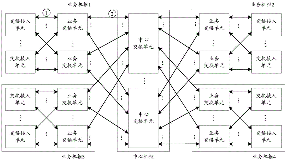
[0111] Figure 11 Shown is a schematic structural diagram of the asymmetric switching system of the third-level switching unit in Embodiment 2 of the present invention, as shown in Figure 11 As shown, the system includes four service chassis 1, 2, 3 and 4, and one central chassis. There are two source switching access units, destination switching access units, and two first-level and third-level switching units on each service frame, and two second-level switching units on the central frame. In this implementation example, only the traffic from service shelf 1 and service shelf 2 to service shelf 3 and service shelf 4 through the central switching box is listed.
[0112] In each service frame, there are two links between the switch access unit and the service switch unit, and there are two links between the service switch unit and the second-level switch unit on ...
Embodiment 3
[0121] This embodiment illustrates link control based on the second-level switching unit.
[0122] The scenario where the second-level switching unit is asymmetrical is as follows: Figure 12 As shown, the second-level switching unit 2# is interconnected with the third-level switching unit 7# and the third-level switching unit 8# each with a high-speed serial link, but due to link abnormalities and other reasons, the second-level switching unit A link between 2# and the third-level switching unit 7# is disconnected, then the second-level switching unit 2# is connected to only one link between the third-level switching unit 8#, then through the second-level The switching unit 2# can only reach the destination switching access unit 7# and the destination switching access unit 8# through only one link with the third-level switching unit 8#. For this situation, the processing steps are as follows:
[0123] Step 001: In the second-level switching unit 2# on the central chassis, th...
PUM
 Abstract
Description
Claims
Application Information