Device for collecting solar energy

A technology of solar energy and equipment, applied in the field of equipment for obtaining solar energy

Inactive Publication Date: 2016-05-11
桑塞考有限公司
View PDF8 Cites 0 Cited by
  • Summary
  • Abstract
  • Description
  • Claims
  • Application Information

AI Technical Summary

Problems solved by technology

However, this means that the equipment must be able to withstand the extreme climatic phen

Method used


Image

  • Device for collecting solar energy

Examples


Embodiment Construction

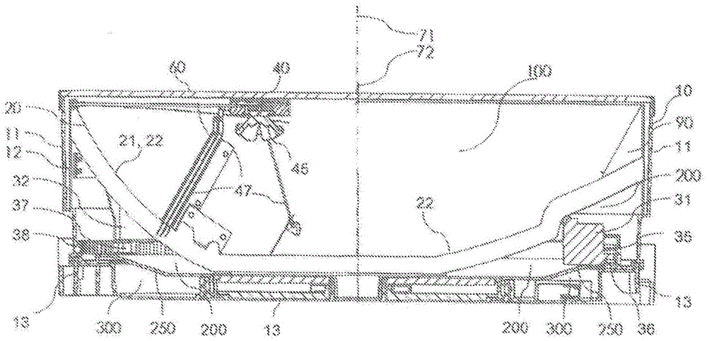
[0017] As fossil fuels decline or become increasingly difficult to recover, while world energy demand shows an upward trend, renewable energy sources are becoming more and more important as additional sources of energy. In this regard, solar energy can be an important factor, if sufficiently high performance and sufficiently high yields can be achieved. The present invention provides a device for harvesting solar energy that can satisfy both aspects at the same time. figure 1 An example of such a device is shown in .

[0018] The device comprises at least an almost completely dust-tight closed housing 10 . A reflective device 20 in the form of a hollow mirror is located within the closed housing 10 . While the mirror 20 may be configured with a single recess, in particular as a hyperbolic reflective surface 21 with a single focal point, this example uses a reflective device having multiple hollow reflective surfaces with a plurality of individual vanes ( lobe). In this exa...


PUM


Abstract

A device for gaining solar energy comprises a integral unit with a casing (10..13). The casing comprises reflection means (20) with a hollow reflector surface (25) and is closed off by refraction means (30) with an entry surface (35) for entering sunlight. The refraction means and reflection means are each rotatably arranged around a rotation axis (71, 72) and their orientation relative to each other is continuously adjusted to the current position of the sun in the sky using positioning means provided for that purpose. The casing comprises a number of dustproof, but nevertheless ventilating chambers. The first chamber (100) is situated between the refraction means (30) and the reflection means (20) and comprises energy-conversion means (40) at least near to the focal point of the reflector surface (25). A second chamber (200) is situated between the reflection means (20) and the base part (13) of the casing and comprises positioning means (51, 53) for rotating the refraction means (30) and the reflection means (20).

Description

technical field [0001] The invention relates to a device for harvesting solar energy, comprising: reflecting means with a reflective surface having at least one focal point; refracting means with an incident surface for sunlight and a reflecting surface facing the reflecting means On the exit surface, the refracting device is arranged to be able to rotate around the first axis of rotation, the reflecting device is arranged to be able to rotate around the second axis of rotation, the incident area of ​​the energy conversion device is arranged to be at least close to at least one focal point of the reflecting surface, and the positioning device is arranged to be configured according to The current position of the sun is used to rotate the refracting means about the first axis of rotation and to rotate the reflecting means about the second axis of rotation. Background technique [0002] Such a device is known from European patent application EP2005074. The device comprises ref...

Claims


Application Information

Patent Timeline
IPC IPC(8): F24J2/06F24J2/08F24J2/10F24J2/54H01L31/052F24S10/40F24S20/30F24S23/00F24S23/30F24S23/70
CPCH01L31/054H02S20/32Y02E10/44Y02E10/52Y02E10/47F24S23/00F24S80/40F24S2023/837F24S30/45F24S2023/84F24S23/31F24S20/30F24S20/61F24S10/40F24S23/70F24S50/20
Inventor 皮特·朋宁罗伊·比吉尔
Owner 桑塞考有限公司
Why Eureka
Try Eureka