
A reciprocating paint spraying machine

A paint sprayer, reciprocating technology, applied in the field of paint sprayers, can solve problems such as poor track operation, uneven paint spraying, and poor gas flow.

Inactive Publication Date: 2018-12-07
KUNSHAN MINGYI CHEM CO LTD
View PDF9 Cites 0 Cited by
  • Summary
  • Abstract
  • Description
  • Claims
  • Application Information

AI Technical Summary

Problems solved by technology

[0002] The existing paint spraying machine structure includes a material conveying track and a spray gun structure arranged above the material. In the actual operation process, the paint sprayed by the spray gun structure acts on the material on the material conveying track, but due to the The gas flow is not smooth, which leads to uneven spraying of the paint surface, and the material conveying track of the existing paint spraying machine structure is easy to accumulate paint. Long-term paint accumulation will make the track run poorly and cause the entire machine to fail

Method used


Image

  • A reciprocating paint spraying machine
  • A reciprocating paint spraying machine
  • A reciprocating paint spraying machine

Examples


Embodiment Construction

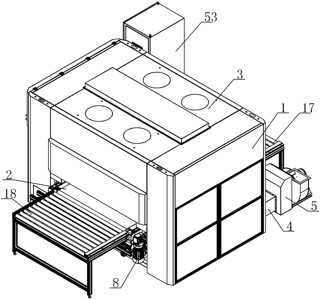
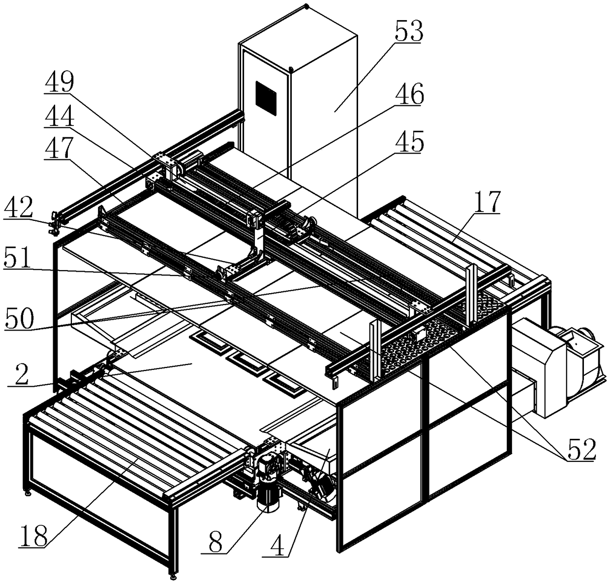
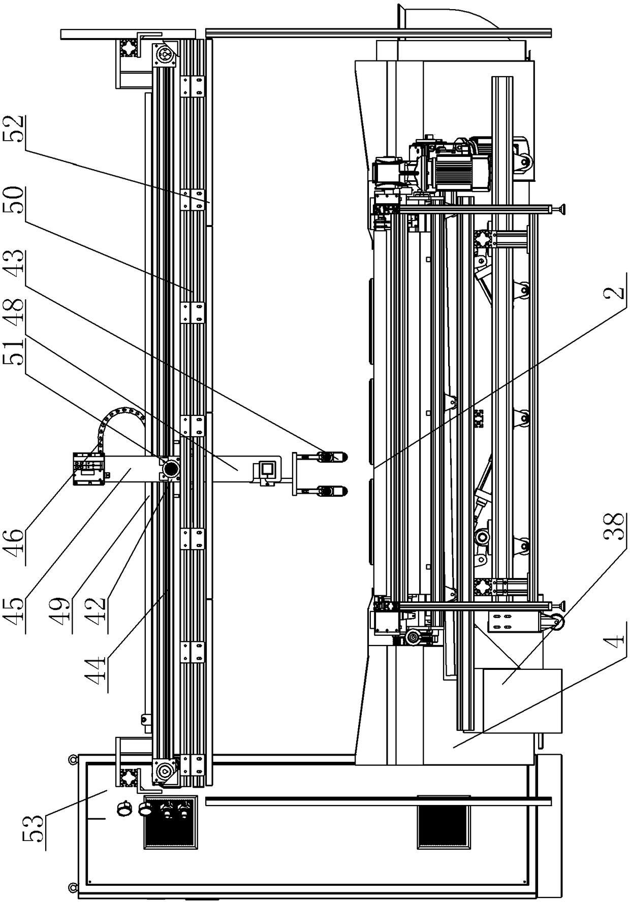
[0030] A reciprocating paint sprayer, see Figure 1 to Figure 9 : It includes a box structure 1, a material conveyor belt 2 is arranged inside the box structure 1, a spray gun structure is arranged above the material conveyor belt 2, and a front bottom wheel scraper structure is arranged directly below the front end of the material conveyor belt 2, and the material conveying There is a bottom scraper structure directly below the middle of the belt 2. The box structure 1 is located directly above the spray gun structure and is equipped with a high-pressure blower 3. The lower part of the box structure 1 is also provided with an air filter box 4. The entrance of the air filter box 4 Opened in the box structure 1, the outlet of the air filter box 4 is externally connected to the centrifugal exhaust fan 5 through the pipeline, and the centrifugal exhaust fan 5 is used to discharge the paint mixed gas in the machine.

[0031] The front end and rear end of the material conveyor belt...


PUM


Abstract

The invention provides a reciprocating type paint spraying machine. The reciprocating type paint spraying machine is provided with an air circulation guiding structure and a paint scraping structure with a conveyer belt, so that the whole paint surface is uniform, no paint is accumulated on a material conveying track, and normal work of the machine is guaranteed. The reciprocating type paint spraying machine comprises a box body structure, the material conveyer belt is arranged inside the box body structure, and a spray gun structure is arranged above the material conveyer belt. The reciprocating type paint spraying machine is characterized in that a front bottom wheel scraper structure is arranged under the front end of the material conveyer belt, a bottom scraper structure is arranged under the middle of the material conveyer belt, a high pressure air feeder is arranged at the position, over the spray gun structure, of the box body structure, an air filtering box is further arranged below the box body structure, an inlet of the air filtering box is opened into the box body structure, an outlet of the air filtering box is externally connected with a centrifugal type exhaust fan through a pipe, and the centrifugal type exhaust fan is used for exhausting paint mixed gas inside the machine.

Description

technical field [0001] The invention relates to the technical field of paint spraying machines, in particular to a reciprocating paint spraying machine. Background technique [0002] The existing paint spraying machine structure includes a material conveying track and a spray gun structure arranged above the material. In the actual operation process, the paint sprayed by the spray gun structure acts on the material on the material conveying track, but due to the The gas flow is not smooth, which leads to uneven spraying of the paint surface, and the material conveying track of the existing paint spraying machine structure is easy to accumulate paint. Long-term paint accumulation will make the track run poorly and cause the entire machine to fail. Contents of the invention [0003] In view of the above problems, the present invention provides a reciprocating paint spraying machine, which is provided with an air circulation guide structure and a paint scraping structure of a...

Claims


Application Information

Patent Timeline
Patent Type & Authority Patents(China)
IPC IPC(8): B05B13/00B05B12/18B05B13/02
CPCB05B12/18B05B13/00B05B13/0221B05B14/00
Inventor 曾智伟
Owner KUNSHAN MINGYI CHEM CO LTD
Learn More