CNC punch array die installation structure

A technology of CNC punching machine and installation structure, which is applied to forming tools, manufacturing tools, safety equipment, etc., can solve the problems affecting the working efficiency of punching machines, the service life of punching energy consumption and die changing structure, the damage of telescopic drive components, and the large energy consumption of CNC punching machines, etc. problem, to achieve the effect of simple structure, increased weight and high stamping frequency

Active Publication Date: 2018-01-02
重庆展坤机电设备有限公司
View PDF5 Cites 0 Cited by
  • Summary
  • Abstract
  • Description
  • Claims
  • Application Information

AI Technical Summary

Problems solved by technology

[0004] Chinese patent CN201520009553.3, titled "Numerical Control Punch", discloses a technical solution for a CNC punch. The CNC punch proposed in this solution completes the processing by high-speed and long-term continuous punching of the punch, and the mold change structure It is installed on the punch that is punched frequently, so the die changing structure also moves up and down following the punch. The weight of the punch itself plus the weight of the die changing structure will cause great energy consumption to the CNC punching machine; the die changing structure follows The punch moves up and down frequently, and when the punch hits downwards at high speed and frequently, it will generate frequent vibrations of more than 20 tons. Since the die change structure is composed of multiple moving parts, intense and frequent vibrations will inevitably lead to damage to the connecting parts, derailment and eventually lead to replacement. If the mold fails, the telescopic drive components and the trachea will also be damaged due to frequent up and down movements and vibrations, and the trachea will be strained and leaked, etc.
The above technical shortcomings have seriously affected the working efficiency of the punch press, stamping energy consumption and the service life of the die change structure.

Method used


Image

  • CNC punch array die installation structure
  • CNC punch array die installation structure
  • CNC punch array die installation structure

Examples


Embodiment 1

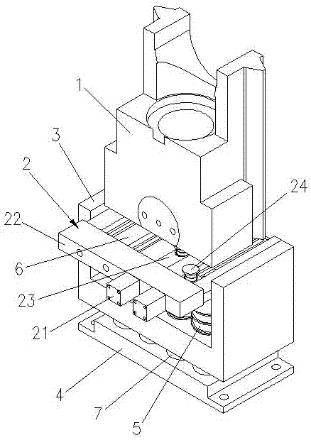
[0035] In practical application, the die changing structure 2 is installed on the upper template 3, and the piston 24 on the die changing structure 2 is arranged in the area between the punch 1 and the upper die assembly 5, and is connected with the punch 1 and the upper die assembly respectively. 5 corresponds. The telescopic drive assembly 21 is installed and fixed on the mounting base 22. One end of the telescopic drive assembly 21 is connected with the connecting piece 23, and the other end of the connecting piece 23 is sleeved with a piston 24, and the elastic assembly on the piston 24 keeps the piston 24 in position. lift up.

[0036] like Image 6 As shown, in the standby state, the punch 1 is at the highest point, and the push rod of the telescopic drive assembly 21 is in a retracted state, and the piston is outside the upper die assembly 5 and the punch 1 at this time. Assuming that the punch 1 is pressed down at this time, since the piston 24 is outside the upper d...

Embodiment 2

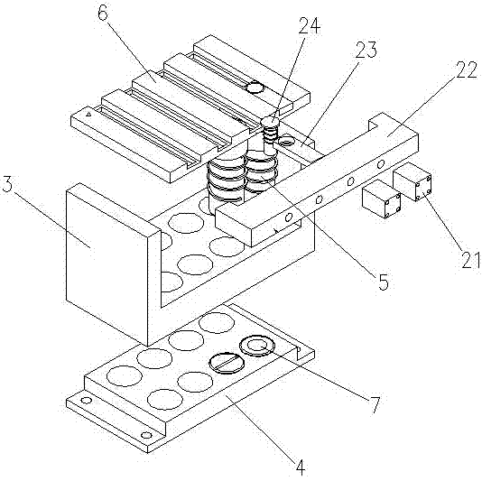
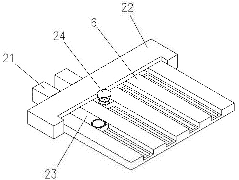
[0040] like figure 1 , figure 2 , image 3 As shown, in practical applications, the end of the piston 24 is slidably sleeved on the piston guide plate 6, and when the telescopic drive assembly 21 pushes the piston 24 to move, the piston 24 is displaced along the chute on the piston guide plate 6, thereby ensuring Accurate displacement positioning of the piston 24. At the same time, the problem of displacement of the piston 24 during the working process is prevented.

Embodiment 3

[0042] like Figure 4 , Figure 5 As shown, in practical applications, the mounting base 22 is provided with a guide hole, the guide hole runs through the mounting base 22, the shape and size of the guide hole correspond to the connector 23, and the connector 23 guides and slides in the guide hole, Thereby, the accurate displacement positioning of the piston 24 is ensured. At the same time, the problem of displacement of the piston 24 during the working process is prevented.


PUM


Abstract

The invention relates to an array type die installation structure of a numerical control press. The array type die installation structure of the numerical control press comprises a punch, a die replacing structure, an upper die plate, a lower die plate, an upper die assembly and a lower die assembly, wherein the upper die assembly is installed on the upper die plate in a sleeving connecting mode; the lower die assembly is fixedly installed in the lower die plate; and the upper die assembly corresponds to the upper die assembly in position. The array type die installation structure of the numerical control press is characterized in that the punch is located above the upper die plate correspondingly and corresponds to the upper die assembly in position; the die replacing structure is composed of a telescopic driving assembly, an installation seat, a connector and a piston, the installation seat is fixedly installed on the upper die plate, the telescopic driving assembly is installed on one side of the upper die plate, is connected with one end of the connector and pushes the connector to move, and the piston is installed at the other end of the connector, is in sliding connection with the connector, and corresponds to the upper die assembly in position. The array type die installation structure of the numerical control press is simple, low in punching energy consumption and high in punching frequency, and the die replacing structure is long in service life.

Description

technical field [0001] The invention relates to parts of a numerical control punching machine, in particular to an array mold installation structure of a numerical control punching machine. Background technique [0002] CNC punching machine is the abbreviation of digital control punching machine, which is an automatic machine tool equipped with a program control system. The control system can logically process and decode programs with control codes or other symbolic instructions, so as to make the punch press move and process parts. [0003] The CNC punching machine can be used for processing various types of metal sheet parts, and can automatically complete a variety of complex hole types and shallow stretch forming processing at one time. The punching method punches large round holes, square holes, waist-shaped holes and various shapes of curved contours, and can also be processed by special processes, such as shutters, shallow stretching, countersinking, flanging holes, ...

Claims


Application Information

Patent Timeline
Patent Type & Authority Patents(China)
IPC IPC(8): B21D37/10B21D37/04B21D55/00
CPCB21D37/04B21D37/10B21D55/00
Inventor 周学晖
Owner 重庆展坤机电设备有限公司
Why Eureka
Try Eureka