Driving structure of clutch of electronic lock

A driving structure and clutch technology, which is applied in the field of electronic locks, can solve the problems of not meeting the installation requirements of anti-theft doors, inconvenient locking, and large door damage, etc., and achieve the effect of convenient and quick unlocking, convenient unlocking, and reduced impact

Inactive Publication Date: 2016-05-18
CHENGDU PUTAISHENG TECH
5 Cites 0 Cited by

AI-Extracted Technical Summary

Problems solved by technology

Fully mechanical anti-theft locks are becoming less and less suitable for modern people's life characteristics due to the inconvenience of locking the door, and have been gradually replaced by electronic anti-theft locks; however, the original electronic lock body is generally thick, wide and large It meets the installation requi...

Method used

As preferably, the elastic metal plate will be selected as the connecting plate 6, so that the shrapnel 8 has certain flexibility when moving up and down with the support seat 5, especially when in contact with the pin, so as to avoid the gap between the active chamber and the passive chamber. The connectors are hard damaged, and the service life of the device is improved.
Shrapnel 8 in use, can directly contact with the bearing pin lower end of six-column rotary clutch, until it is pushed in the square hole on the clutch, realizes the linkage between handle and clutch, as preferably, shrapnel 8 The arc length is a quarter of the circumference of the circle where it is located, which can ensure the continuity when multiple pins enter the square holes respectively, avoid the synchronization of the rotation of the handle and the linkage of the clutch, and facilitate quick unlocking.
Shrapnel 8 selects arc-shaped for use, can make two adjacent pins on the clutch maintain continuity in the contact with square hole, and by the mode of electronic unlocking and mechanical unlocking, in bringing convenient and quick way of unlocking At the same time, the practical performance of the lock body is improved, and the handle is always in...

Abstract

The invention discloses a driving structure of a clutch of an electronic lock. The driving structure comprises a base and a spring plate; the bottom part of the spring plate is provided with a supporting seat; the lower end of the supporting seat penetrates through the upper wall of the base and is arranged in a passive cavity; a motor and a screw are also arranged in the passive cavity; the upper end part of the screw is glidingly arranged in a first blind hole; the screw is provided with a supporting block which is in screw-thread fit with the screw; a groove is formed in each of two sides of the upper end of the supporting block; the lower end face of the supporting seat is provided with protrusions separately matched with the grooves; a connecting joint is arranged in an active cavity; the lower end face of the connecting joint is provided with an upper ejector pin; the upper ejector pin penetrates through the lower cavity body wall of the active cavity and extends outwards; one end of a connecting rod is glidingly arranged in a second blind hole; and the other end of the connecting rod penetrates through the upper cavity body wall of the active cavity and extends outwards. In a manner of electronic unlocking and mechanical unlocking, practical performance of a lock body is increased; moreover, a handle is in an idling condition all the time in a door closed state, so that a lawless person cannot open the lock outdoors or indoors through the handle, and safety performance of the lock body is enhanced.

Application Domain

Technology Topic

Image

  • Driving structure of clutch of electronic lock

Examples

  • Experimental program(1)

Example Embodiment

[0019] Example 1
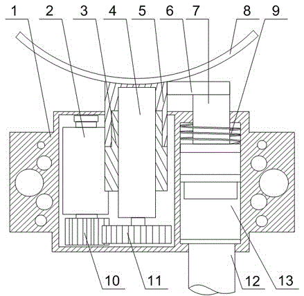
[0020] Such as figure 1 As shown, this embodiment includes a base 1 and an elastic piece 8. The inside of the base 1 is divided into an active cavity and a passive cavity. The elastic piece 8 is in the shape of an arc. The bottom of the elastic piece 8 is provided with a support seat 5, and the lower end of the support seat 5 penetrates The upper wall of the base 1 is placed in the passive cavity. A motor 2 and a screw 4 are also arranged in the passive cavity. A small gear 10 is installed on the output end of the motor 2, and a large gear 11 matched with a small gear 10 is installed at the lower end of the screw 4 and supports A first blind hole is opened at the lower end of the seat 5, and the upper end of the screw 4 is slidably arranged in the first blind hole. The screw 4 is equipped with a supporting block 3 threaded with it. Groove, the lower end surface of the support base 5 is provided with a protrusion matching the groove, a connector 13 is provided in the active cavity, a second blind hole is opened on the upper end surface of the connector 13, and the lower end surface of the connector 13 An upper mandrel 12 is provided, and the upper mandrel 12 extends through the lower cavity wall of the active cavity. One end of the connecting rod 7 is slidably arranged in the second blind hole, and the other end of the connecting rod 7 penetrates the upper cavity wall of the active cavity Extending outwards, it also includes a connecting plate 6, one end of the connecting plate 6 is connected with the upper end surface of the connecting rod 7, and the other end of the connecting plate 6 is connected with the side wall of the support base 5.
[0021] When working, the device directly cooperates with the six-post rotary clutch of the electronic lock. When the door is closed, the clutch is in idling rotation and the handle cannot open the door lock. When the door needs to be opened, the electronic signal is transmitted to the cylinder connected to the end of the upper mandrel 12. The output end of the cylinder is pushed out, so that the connecting head 13 in the active cavity drives the connecting rod 7 to move upwards. At the same time, the connecting plate 6 and the supporting seat 5 also move upwards together with the connecting rod 7, so that the elastic sheet 8 is upward in the vertical direction. Until the shrapnel 8 is in contact with the pin of the six-post rotating clutch and pushes it into the square hole, so that the clutch and the handle become an integral transmission linkage to achieve unlocking; and when the electronic circuit or the cylinder is damaged, With the mechanical emergency key, the motor 2 in the passive cavity starts to run, the motor 2 rotates, so that the pinion 10 and the big gear 11 begin to rotate and cooperate, and the screw 4 starts to rotate, and at this time the support base 5 and the support block 3 in the passive cavity They are snapped together, and the support base 5 is also restricted by the connecting plate 6 and the connecting rod 7 and cannot rotate together with the screw 4, that is, relative movement between the support block 3 and the screw 4, the support block 3, the support base 5 , The elastic piece 8, the connecting plate 6 and the connecting rod 7 all begin to move upwards, and the elastic piece 8 pushes the pin to move upward, so that the six-post rotary clutch is linked with the square hole to realize unlocking.
[0022] The shrapnel 8 selects an arc shape, which can make the two adjacent pins on the clutch maintain continuity in contact with the square hole, and through the electronic unlocking and mechanical unlocking methods, it brings a convenient and quick unlocking method while improving The practical performance of the lock body, and the handle is always in an idling state when the door is closed, so that criminals cannot use the handle to open the lock outdoors or indoors, enhancing the safety performance of the lock body.
[0023] This embodiment also includes a spring 9, one end of the spring 9 is connected to the upper wall of the active cavity, and the other end of the spring 9 is connected to the upper end surface of the connector 13. Whether it is electronic unlocking or mechanical start, the lower end of the connecting rod 7 will always move up and down in the active cavity. Therefore, the lower end of the connecting rod 7 will cause a continuous impact on the second blind hole, and the upper end connected to the connecting head 13 The rod 12 will transmit the applied stress to the cylinder, thereby causing the performance of the cylinder to be unstable. To solve this problem, the present invention is provided with a spring 9, that is, during the process of the upper ejector rod 12 moving up or the connecting rod 7 automatically moving down, The spring 9 offsets the impact force generated by the downward movement of the connecting rod 7 through a certain elastic deformation, so as to reduce the impact on the power components of the driving device and prolong its service life.
[0024] During use, the shrapnel 8 will directly contact the lower end of the pin of the six-column rotating clutch until it is pushed into the square hole on the clutch to realize the linkage between the handle and the clutch. As a preference, the arc length of the shrapnel 8 It is a quarter of the circumference of the circle where it is located, which can ensure the continuity when multiple pins enter the square hole respectively, avoid the synchronization of the rotation of the handle and the linkage of the clutch, and facilitate quick unlocking.
[0025] Preferably, an elastic metal plate is selected as the connecting plate 6, so that the elastic sheet 8 has a certain flexibility when it moves up and down with the support base 5, especially when it comes into contact with the pin, and avoids the connection between the active cavity and the passive cavity. Hard damage occurs, which increases the service life of the device.

PUM

no PUM

Description & Claims & Application Information

We can also present the details of the Description, Claims and Application information to help users get a comprehensive understanding of the technical details of the patent, such as background art, summary of invention, brief description of drawings, description of embodiments, and other original content. On the other hand, users can also determine the specific scope of protection of the technology through the list of claims; as well as understand the changes in the life cycle of the technology with the presentation of the patent timeline. Login to view more.

Similar technology patents

Plastic pipe cooling device

InactiveCN107498827AGuaranteed effect and qualityImprove practical performanceTubular articlesVacuum coolingSizing
Owner:JIANGSU GERON PIPE IND

A storage device used for engineering costs

InactiveCN107280194AAvoid lack of storage capacityImprove practical performanceLuggageOther accessoriesSoftware engineering
Owner:GUANGZHOU SONGBIN ENG TECH CO LTD

Classification and recommendation of technical efficacy words

  • Improve practical performance
  • Improve safety performance

Electric monocycle

InactiveCN104760644AImprove safety performanceAdaptable to road conditionsUnicyclesBicyclesVehicle frameEngineering
Owner:UNIV OF SHANGHAI FOR SCI & TECH
Why Eureka
Try Eureka