Optical fiber distribution frame

An optical fiber distribution frame and distribution frame technology, applied in the direction of fiber mechanical structure, etc., can solve the problems of inability to achieve, easy installation and use, waste of space, etc., and achieve the effect of cabling layout and convenient installation.

Inactive Publication Date: 2016-05-18
TIANJIN XINYUN NETWORK TECH
View PDF0 Cites 0 Cited by
  • Summary
  • Abstract
  • Description
  • Claims
  • Application Information

AI Technical Summary

Problems solved by technology

Now optical communication has been widely used in long-distance trunk lines and local network transmission, and higher requirements have been put forward for its capacity, function and structure. The existing distribution frames have certain shortcomings and deficiencies, mainly in the following aspects: : The frame structure of the distribution frame has closed type, semi-closed type and open type, each has advantages and disadvantages, can not achieve dustproof, good heat dissipation effect, and can also be easy to install and use; in the process of use, because the optical fiber line cannot be bent at will Transformation results in unreasonable use of space and waste of space; these not only make it difficult to install and maintain distribution cables or connecting cables, but also bring inconvenience to the expansion and upgrading of later equipment

Method used


Image

  • Optical fiber distribution frame
  • Optical fiber distribution frame
  • Optical fiber distribution frame

Examples


Embodiment Construction

[0020] Specific embodiments of the present invention are described below in conjunction with accompanying drawing:

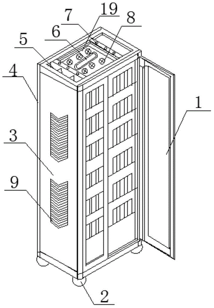
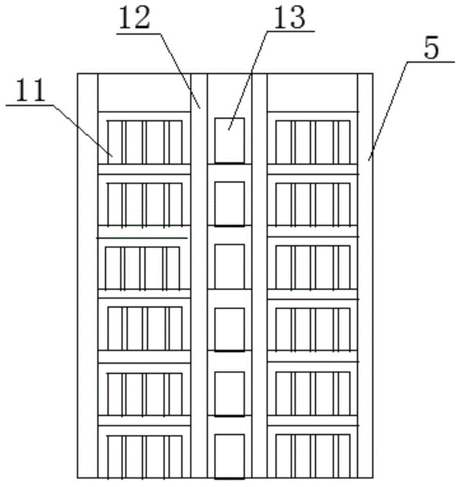
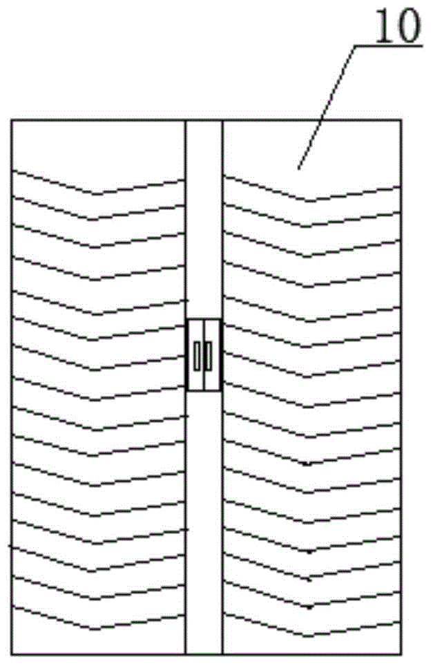
[0021] Such as Figures 1 to 4 As shown, an optical fiber distribution frame includes a distribution frame main body 4, a front door 1, a side plate 3, a rear door 10, a top fixing hole 7, a distribution box frame 11, a top plate 19, a bottom plate 16 and a bottom fixing hole 17, and Including pulley 2, side vertical wiring trough 5, coil ring 6, middle vertical wiring trough 12 and annular wiring trough 15; the front door 1, side plate 3 and rear door 10 are respectively fixed on the distribution frame main body 4 Front, side and rear; the top fixing hole 7 is on the top plate 19; the bottom fixing hole 17 is on the bottom plate 16; the wiring box frame 11 passes through the top fixing hole 7 and the bottom The fixing holes 17 are connected up and down with the distribution frame main body 4; the pulleys 2 are fixed on the four corners of the bottom plate 16; ...


PUM


Abstract

The invention provides an optical fiber distribution frame which comprises a distribution frame body, a front door, a side plate, a rear door, top fixing holes, a distribution box rack, a top plate, a bottom plate and bottom fixing holes, and further comprises pulleys, a side vertical wire duct, a coiling ring, an intermediate vertical wire duct and an annular wire duct. The front door, the side plate and the rear door are fixed to the front, the side and the back of the distribution frame body respectively. The top fixing holes are arranged in the top plate. The bottom fixing holes are arranged in the bottom plate. The distribution box rack is connected with the top and the bottom of the distribution frame body through the top fixing holes and the bottom fixing holes respectively. The pulleys are fixed to the four corners of the bottom plate. The side vertical wire duct is fixed to the side of the distribution frame body. The intermediate vertical wire duct is fixed to the center of the distribution box rack. The annular wire duct is fixed to the bottom plate. The optical fiber distribution frame is simple in structure, and can easily achieve connection, distribution and scheduling of an optical fiber line.

Description

technical field [0001] The invention relates to the technical field of optical communication equipment, in particular to an optical fiber distribution frame. Background technique [0002] Optical fiber distribution frame is an important supporting equipment in the optical transmission system. It is mainly used for optical fiber fusion at the end of the optical cable, installation of optical connectors, adjustment of optical paths, storage of redundant pigtails, and protection of optical cables. The safe operation and flexible use of communication networks play an important role. Now optical communication has been widely used in long-distance trunk lines and local network transmission, and higher requirements have been put forward for its capacity, function and structure. The existing distribution frames have certain shortcomings and deficiencies, mainly in the following aspects: : The frame structure of the distribution frame has closed type, semi-closed type and open type,...

Claims


Application Information

Patent Timeline
Patent Type & Authority Applications(China)
IPC IPC(8): G02B6/44
Inventor 吕秉卓
Owner TIANJIN XINYUN NETWORK TECH
Why Eureka
Try Eureka