Al technical title is built by PatSnap Al team. It summarizes the technical point description of the patent document.
A technology of liquid crystal display device and liquid crystal layer, which is applied in nonlinear optics, instruments, optics, etc., can solve the problems of unfavorable cost and difficulty in using "viewing angle compensation plate integrated polarizing plate".
Active Publication Date: 2016-05-18
STANLEY ELECTRIC CO LTD
View PDF7 Cites 2 Cited by
Summary
Abstract
Description
Claims
Application Information
AI Technical Summary
This helps you quickly interpret patents by identifying the three key elements:
Problems solved by technology
Method used
Benefits of technology
Problems solved by technology
However, in the case of employing a structure based on a known technology, it is difficult to use the above-ment
Method used
Image
Click on the blue label to locate the original text in one second.
Reading with bidirectional positioning of images and text.
Examples
Embodiment 1
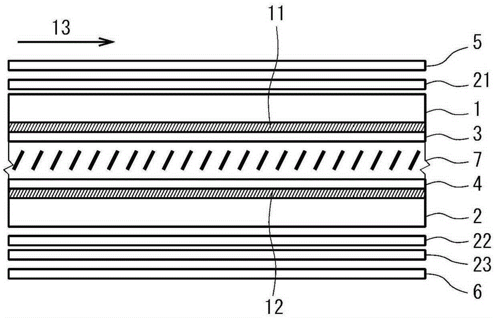
[0057] ·Is the above figure 1 , 2 In the structure shown in , a TAC film as a protective film of the polarizing plate is disposed between the polarizing layer of the polarizing plate and the optical plate
[0058] ·Liquid crystal layer thickness: 4μm
[0059] ·Liquid crystal material: △n=0.0914, △ε=-5.1, no chiral material added
[0060] ・Pretilt angle: 89.5 degrees (the first substrate and the second substrate both have this pretilt angle)
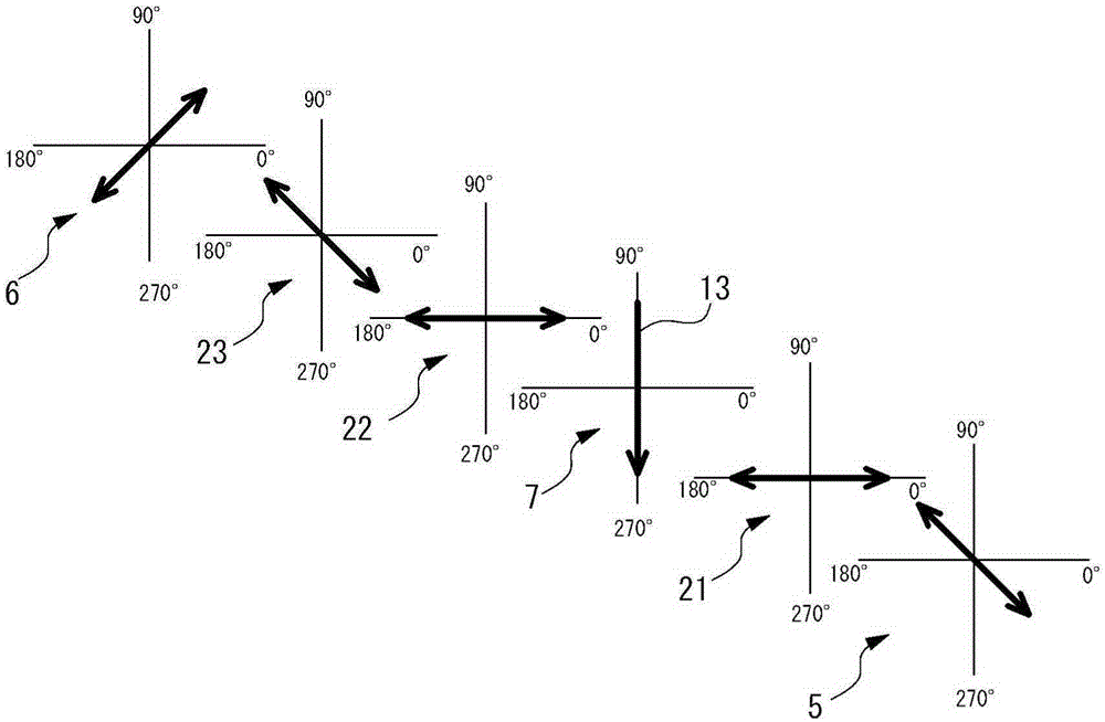
[0061] ・Alignment direction at the center of the layer thickness direction of the liquid crystal layer when a voltage is applied: 6 o'clock direction (270° direction)
[0062] 1 / 4 wavelength plate: a retardation plate with an in-plane retardation of 140nm and positive uniaxial optical anisotropy (positive A plate)
[0063] ・Optical plate: Negative biaxial film with in-plane retardation of 55nm and thickness direction retardation of 220nm
[0064] Light source: standard light source D65
[0065] ・Emulator: Liquid crystal display emul...
Embodiment 2
[0067] ·Is the above figure 1 , 2 In the structure shown in , no TAC film, etc. as a protective film of the polarizing plate is placed between the polarizing layer of the polarizing plate and the optical plate
[0068] ·Other conditions are identical with embodiment 1
Embodiment 3
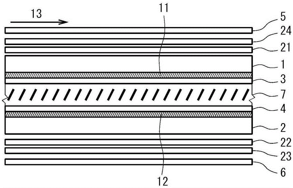
[0070] ·Is the above image 3 , 4 In the structure shown in , no TAC film, etc. as a protective film of the polarizing plate is placed between the polarizing layer of the polarizing plate and the optical plate
[0071] ・Optical plate: Negative biaxial film with in-plane retardation of 55nm and thickness direction retardation of 124nm
[0072] ·Other conditions are identical with embodiment 1
PUM
Abstract
The invention provides a liquid crystal display device which can restrain color offset of a normally white displayed vertical oriented liquid crystal display device in observation in a left-and-right direction. The liquid crystal display device is provided with a first substrate, a second substrate, a liquid crystal layer, a first polarizing plate, a second polarizing plate, a first optical board, a second optical board and a third optical board. The absorption axes of the polarizing plates are configured approximately perpendicular with one another. Furthermore each polarizing plate is configured at an angle of approximate 45 DEG relative to the orienting direction of an approximately central part in the layer thickness direction of the liquid crystal layer when an electric field is applied. The first optical board is a 1/4 wavelength board, and the in-surface slow axis is configured at an angle of approximate 45 DEG relative to the absorption axis of the first polarizing plate. The second optical board is a 1/4 wavelength board, and the in-surface slow axis is configured at an angle of approximate 45 DEG relative to the absorption axis of the second polarizing plate. The third optical board has negative biaxial optical anisotropy, and the in-surface slow axis is configured to be approximately perpendicular with the absorption axis of the first polarizing plate.
Description
technical field [0001] The present invention relates to a vertical alignment type liquid crystal display device. Background technique [0002] The basic configuration of a vertical alignment liquid crystal display device includes two substrates facing each other, a vertical alignment liquid crystal layer provided between these substrates, and two polarizing plates respectively arranged outside the substrates. In this vertical alignment type liquid crystal display device, the absorption axes of the two polarizing plates are arranged to be perpendicular to each other (crossed Nicol arrangement), and a viewing angle compensating plate is arranged between the substrate and the polarizing plates, thereby, Very good dark display can be obtained when viewed from the front and when viewed from an oblique direction, and excellent normally black display can be realized. [0003] In such a vertical alignment type liquid crystal display device, by further providing a reflection plate o...
Claims
Application Information
Patent Timeline
Application Date:The date an application was filed.
Publication Date:The date a patent or application was officially published.
First Publication Date:The earliest publication date of a patent with the same application number.
Issue Date:Publication date of the patent grant document.
PCT Entry Date:The Entry date of PCT National Phase.
Estimated Expiry Date:The statutory expiry date of a patent right according to the Patent Law, and it is the longest term of protection that the patent right can achieve without the termination of the patent right due to other reasons(Term extension factor has been taken into account ).
Invalid Date:Actual expiry date is based on effective date or publication date of legal transaction data of invalid patent.