Liquid crystal display device

A technology of liquid crystal display device and liquid crystal layer, which is applied in the directions of instruments, nonlinear optics, optics, etc., can solve problems such as cost increase, and achieve the effect of suppressing color shift and low cost

Active Publication Date: 2020-10-09
STANLEY ELECTRIC CO LTD
View PDF4 Cites 0 Cited by
  • Summary
  • Abstract
  • Description
  • Claims
  • Application Information

AI Technical Summary

Problems solved by technology

However, it is conceivable that adding the above-mentioned viewing angle compensating plate will lead to an increase in cost, which is disadvantageous.

Method used


Image

  • Liquid crystal display device
  • Liquid crystal display device
  • Liquid crystal display device

Examples


Embodiment 1

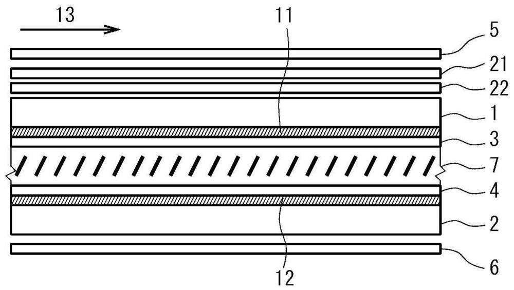
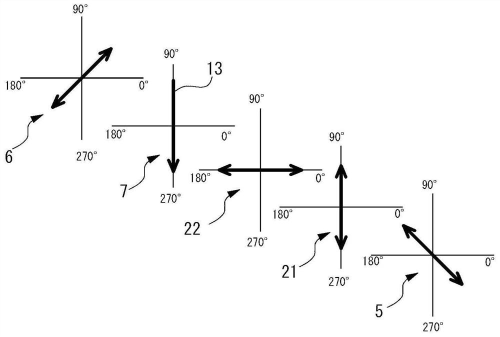
[0074] ・Structure of the liquid crystal display device: the structure of the first embodiment (see figure 1 and figure 2 )

[0075] ・First optical plate: An optical plate with an in-plane phase difference of 55 nm, a thickness direction phase difference of 220 nm, and negative biaxial optical anisotropy

[0076] ・Second optical plate: An optical plate with an in-plane retardation of 330 nm and positive uniaxial optical anisotropy

[0077] Figure 12(A) is a graph showing the calculation results of the spectroscopic spectrum of Example 1. As shown in the figure, in the liquid crystal display device of Example 1, when viewed from the front and when viewed at a polar angle of 50°, the following trend can be seen: Compared with the case of the above-mentioned comparative example, the transmittance on the short-wavelength side changes. The change in transmittance is small and the long-wavelength side is large. Among them, although the difference in transmittance between spect...

Embodiment 2

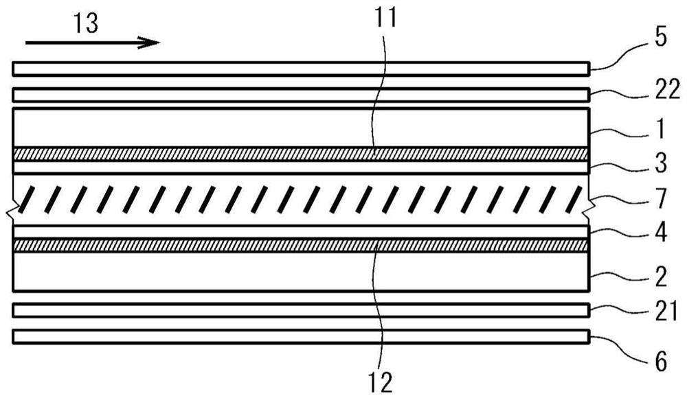
[0079] ・Structure of the liquid crystal display device: the structure of the second embodiment (see image 3 and Figure 4 )

[0080] ・First optical plate: An optical plate with an in-plane phase difference of 55 nm, a thickness direction phase difference of 220 nm, and negative biaxial optical anisotropy

[0081] ・Second optical plate: An optical plate with an in-plane retardation of 330 nm and positive uniaxial optical anisotropy

[0082] Figure 12 (B) is a graph showing the calculation results of the spectroscopic spectrum in Example 2. As shown in the figure, also in the liquid crystal display device of Example 2, the same spectroscopic spectrum as that of the above-mentioned Example 1 was obtained, so it is considered that the change in color tone with respect to the change in viewing angle is suppressed as compared with the comparative example.

Embodiment 3

[0084] ・Structure of the liquid crystal display device: the structure of the second embodiment (see image 3 and Figure 4 )

[0085] ・First optical plate: An optical plate with an in-plane phase difference of 55 nm, a thickness direction phase difference of 220 nm, and negative biaxial optical anisotropy

[0086] ・Second optical plate: An optical plate with an in-plane retardation of 255 nm and positive uniaxial optical anisotropy


PUM

PropertyMeasurementUnit
angleaaaaaaaaaa

Abstract

The invention provides a liquid display device capable of suppressing color offset of a normally-white display vertical orientation liquid display device with a low cost when being viewed from the left and right direction. The liquid display device is provided with a first substrate, a second substrate, a liquid layer, a first polarization plate, a second polarization plate, a first to a third optical boards. The absorption axes of the polarization plates are substantially orthogonal, and are in 45 degrees to the orientation direction of the substantial center of the thickness direction of the liquid layer to which an electric field is applied. The first optical board is provided with negative biax optical aeolotropism and has an in-plane phase difference Re1 from 40 to 70nm. The in-plane slow axis of the first optical board is 45 degrees relative to the absorption axis of the first optical board. The second polarization plate is provided with positive single-axis optical aeolotropism. The in-plane slow axis of the second optical board is 45 degrees relative to the absorption axis of the first optical board. The in-plane phase difference Re2 of the second optical board has a relation that Re2-Re1 is greater than or equal to 200nm but less than or equal to 320nm.

Description

technical field [0001] The present invention relates to a vertical alignment type liquid crystal display device. Background technique [0002] The basic configuration of a vertical alignment liquid crystal display device includes two substrates facing each other, a vertical alignment liquid crystal layer provided between these substrates, and two polarizing plates respectively arranged outside the substrates. In this vertical alignment type liquid crystal display device, the absorption axes of the two polarizing plates are arranged to be perpendicular to each other (crossed Nicol arrangement), and a viewing angle compensating plate is arranged between the substrate and the polarizing plates, thereby, Very good dark display can be obtained when viewed from the front and when viewed from an oblique direction, and excellent normally black display can be realized. [0003] In such a vertical alignment type liquid crystal display device, by further providing a reflection plate o...

Claims


Application Information

Patent Timeline
Patent Type & Authority Patents(China)
IPC IPC(8): G02F1/1335G02F1/13363
CPCG02F1/133528G02F1/13363G02F1/133531
Inventor 岩本宜久
Owner STANLEY ELECTRIC CO LTD
Why Eureka
Try Eureka