Led Illumination Device And Led Light-emission Module

A technology for lighting devices and light-emitting modules, which is applied to lighting devices, fixed lighting devices, components of lighting devices, etc., can solve the problems of color temperature shift, inability to adjust the color of lighting light to the correct color temperature, etc.

Inactive Publication Date: 2014-06-25
PANASONIC INTELLECTUAL PROPERTY MANAGEMENT CO LTD
View PDF7 Cites 0 Cited by
  • Summary
  • Abstract
  • Description
  • Claims
  • Application Information

AI Technical Summary

Problems solved by technology

Therefore, when the light emitting unit transmits the output light adjusted to the target color once through the optical member, the color temperature may shift, and the illumination light may not be adjusted to the correct color temperature.

Method used


Image

  • Led Illumination Device And Led Light-emission Module
  • Led Illumination Device And Led Light-emission Module
  • Led Illumination Device And Led Light-emission Module

Examples


Embodiment approach 1

[0044] (Overall structure of LED lighting device 1)

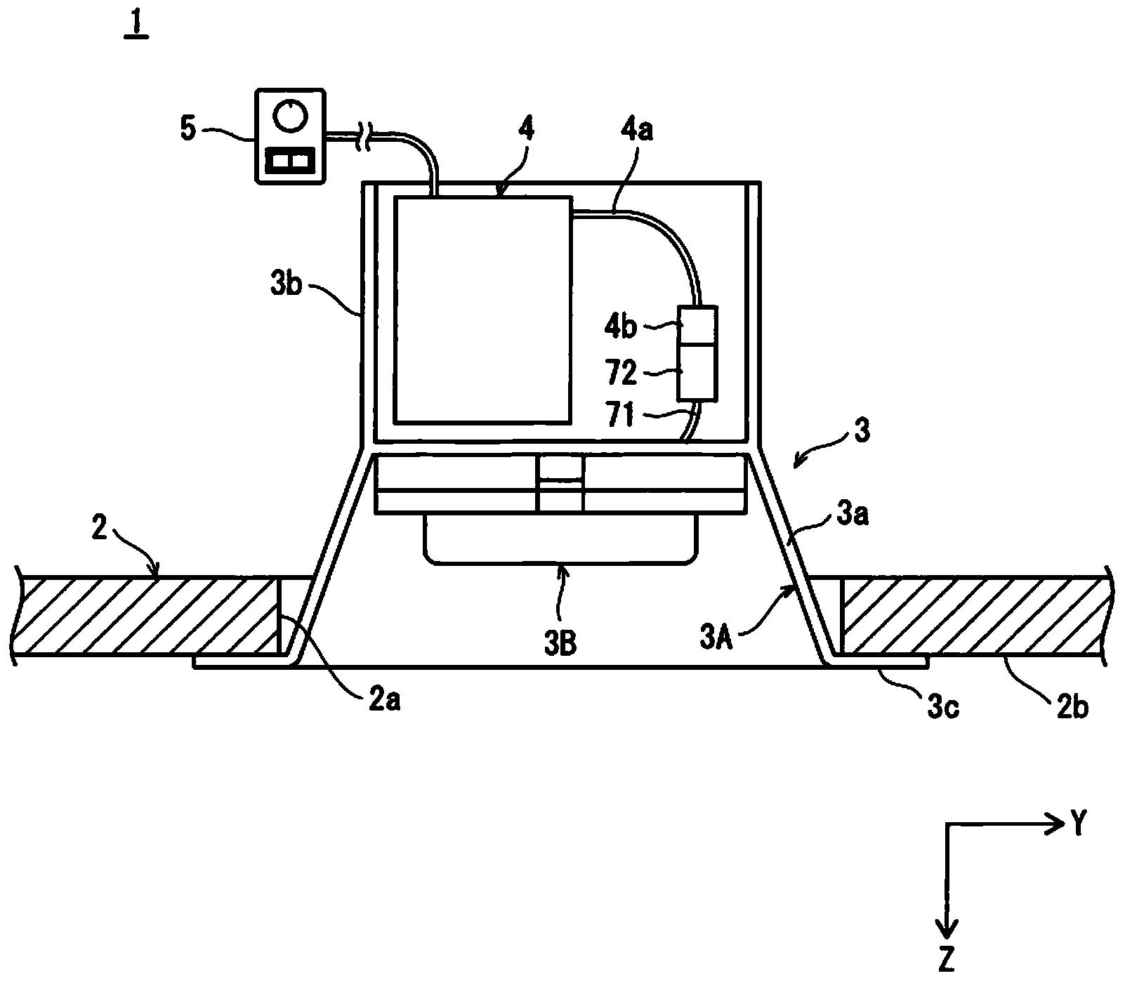
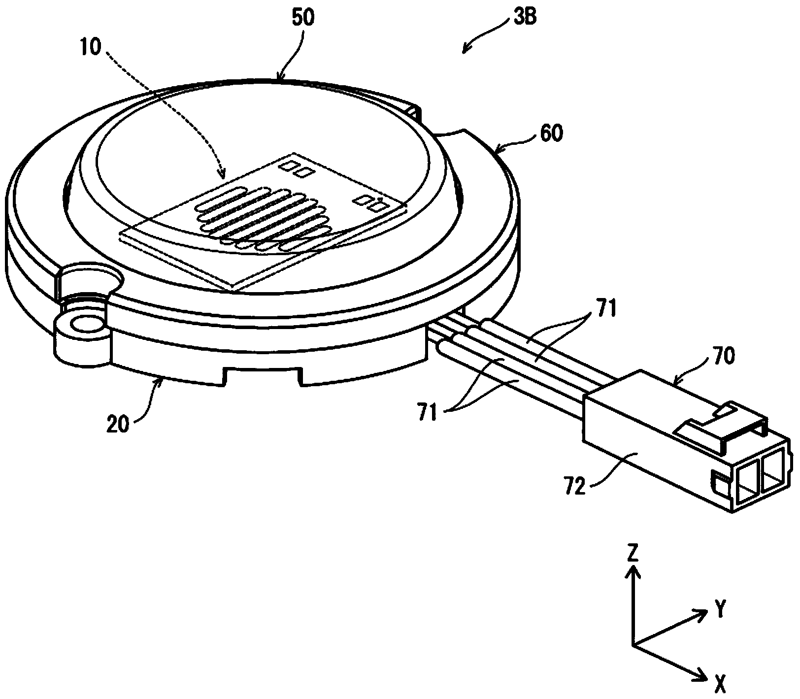
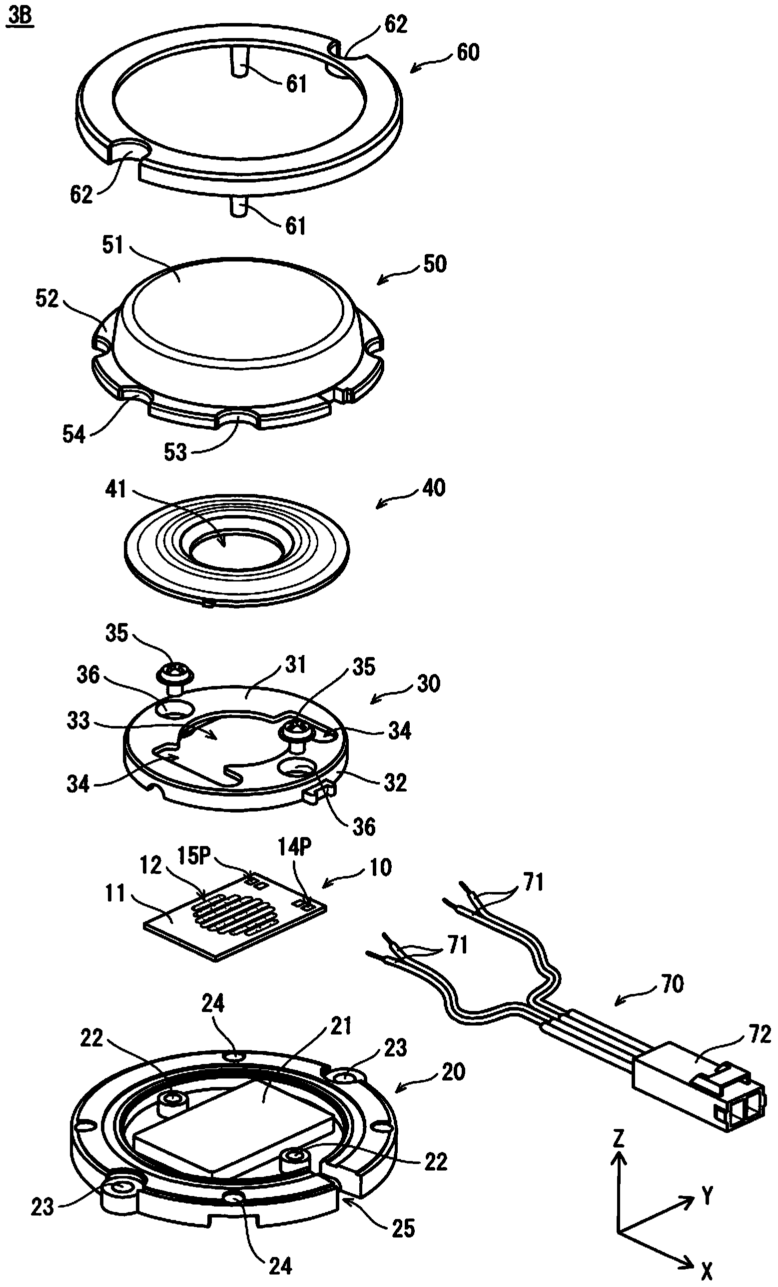
[0045] figure 1 It is a cross-sectional view showing the structure of an LED lighting device 1 (hereinafter simply referred to as "device 1") according to Embodiment 1 of the present invention. figure 2 It is a perspective view showing the external structure of the lamp unit 3B. image 3 It is an exploded perspective view showing the internal structure of the lamp unit 3B. Figure 4 It is a figure which shows the structure of the light emitting module 10. Figure 5It is a wiring diagram showing the connection relationship of the light emitting module 10 , the circuit unit 4 , and the dimming unit 5 .

[0046] The device 1 includes a lighting fixture 3 , a circuit unit 4 , and a dimming unit 5 . Such as figure 1 As shown, the device 1 is, as an example, a downlight type (ceiling lamp) embedded in the embedding hole 2 a of the ceiling 2 .

[0047] (lighting fixture 3)

[0048] The lighting fixture 3 includes a fixtu...

Embodiment approach 2

[0155] Next, Embodiment 2 of the present invention will be described focusing on differences from Embodiment 1. FIG. Figure 11 It is an exploded perspective view showing the internal structure of 3 C of lamp units of the lighting fixture of Embodiment 2. Figure 12 It is a wiring diagram showing the connection relationship of the light emitting modules 10A, 10B, the circuit unit 4 , and the dimming unit 5 .

[0156] The difference from the lamp unit 3B is that, as Figure 11 As shown, the first light emitting part 12a and the second light emitting part 12b having different color temperatures are separated and mounted in the light emitting modules 10A and 10B independently, respectively.

[0157] Such as Figure 12 As shown, the light emitting module 10A is provided with terminal portions 14A, 15A and wiring 16A, 17A. Element array 12a of first light emitting unit 12a 1 ~12a 4 The connection is made by the wirings 16A, 17A so that the number of serial connections constitu...


PUM


Abstract

An illumination device and a light-emission module suppressing a change in color temperature when light emitted from a light-emission unit passes through an optical member. The illumination device (3) has a lighting apparatus that includes: a first light-emission part (12a) emitting light of a daylight color temperature; a second light-emission part (12b) emitting light of an incandescent lamp color temperature; and the optical member (50), which is disposed on an optical path of the light emitted from the light-emission parts (12a, 12b). A correlated color temperature of the light emitted from the second light-emission part (12b) is set to 2238 K. Due to this, in a spectrum of the light emitted from the second light-emission part (12b), a maximum intensity within a wavelength range from 400 nm to 500 nm is no greater than one-tenth of a maximum intensity within a wavelength range from 300 nm to 800 nm.

Description

technical field [0001] The present invention relates to a lighting device and a light-emitting module using LEDs as a light source, and particularly relates to a technique for preventing color shift when a plurality of light sources are used for color adjustment. Background technique [0002] LED lighting devices of various forms such as down light type and desk stand type using LED (Light Emitting Diode) as a light source have been developed (for example, refer to Patent Document 1). [0003] In an LED lighting device, as an example, there are: a light-emitting module including a plurality of light-emitting parts with different color temperatures; The lighting circuit of the light-emitting element of each light-emitting part. The light emitting unit has a light emitting element as an LED, and a wavelength conversion member arranged to cover the light emitting element. The wavelength conversion member contains a phosphor, and converts the wavelength of a part of the light ...

Claims


Application Information

Patent Timeline
Patent Type & Authority Applications(China)
IPC IPC(8): F21S2/00F21V9/16F21Y101/02F21V9/40H05B44/00
CPCF21K9/90F21K9/56H01L33/504F21V9/10F21S8/026F21Y2105/12F21Y2105/10F21K9/64F21Y2115/10F21Y2113/13H05B45/20
Inventor 绪方俊文石森淳允阿部益巳山口博司和田恭典
Owner PANASONIC INTELLECTUAL PROPERTY MANAGEMENT CO LTD
Why Eureka
Try Eureka