Control device of engine, control device of engine and hydraulic pump, and control device of engine, hydraulic pump, and generator motor

a technology of control device and engine, which is applied in the direction of electrical control, electric generator control, and fluid couplings. it can solve the problems of large fuel consumption, low pump efficiency, and large fuel consumption, so as to avoid the effect of lowering the assist force of the engine 2, avoiding the lowering of the engine revolution in time of switching

Inactive Publication Date: 2009-12-31
KOMATSU LTD
View PDF3 Cites 84 Cited by
  • Summary
  • Abstract
  • Description
  • Claims
  • Application Information

AI Technical Summary

Benefits of technology

[0085]According to the sixteenth invention, as shown in FIG. 19, immediately after switching from the engine torque assist operation state to the power generating operation state corresponding to the requested power generation amount, a control to gradually change the power generation torque of the generator motor 11 from the torque at the termination of assistance to the power generation torque corresponding to the requested power generation amount of the generator motor 11 is performed, and thus change in power generation torque of the generator motor 11 in switching from the engine torque assist operation to the power generating operation state corresponding to the requested power generation amount becomes smooth. The lowering in engine revolution in time of switching is thereby avoided.
[0086]According to the seventeenth invention, as shown in FIG. 16, the third maximum torque curve L3 in which the maximum absorption torque (third pump maximum absorption torque) Tpcommax) of the hydraulic pump 3 gradually decreases with decease in the torque upper limit value Tgencom2 of the generator motor 11 is set in the third pump maximum absorption torque calculating unit 106. According to the twelfth invention, the capacity of the hydraulic pump 3 is controlled so that the maximum absorption torque of the hydraulic pump 3 gradually decreases according to decrease in the torque upper limit value of the generator motor 11, and thus the absorption torque of the hydraulic pump 3 lowers with lowering in t

Problems solved by technology

Thus, problems in that the fuel consumption rate is large (bad) and the pump efficiency is low arise when performing the work with the engine revolution n fixed at a substantially constant high revolution.
As also apparent from FIG. 2, the regulation line Fe corresponds to a region where the fuel consumption is relatively large on the equal fuel consumpt

Method used


Image

  • Control device of engine, control device of engine and hydraulic pump, and control device of engine, hydraulic pump, and generator motor
  • Control device of engine, control device of engine and hydraulic pump, and control device of engine, hydraulic pump, and generator motor
  • Control device of engine, control device of engine and hydraulic pump, and control device of engine, hydraulic pump, and generator motor

Examples


first example

[0162]First, the first example will be described.

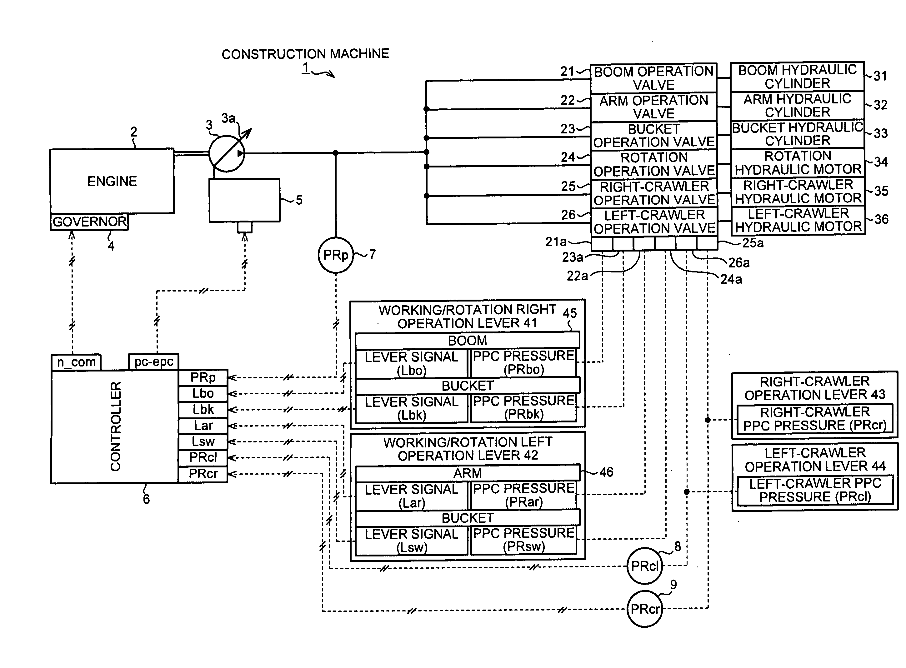
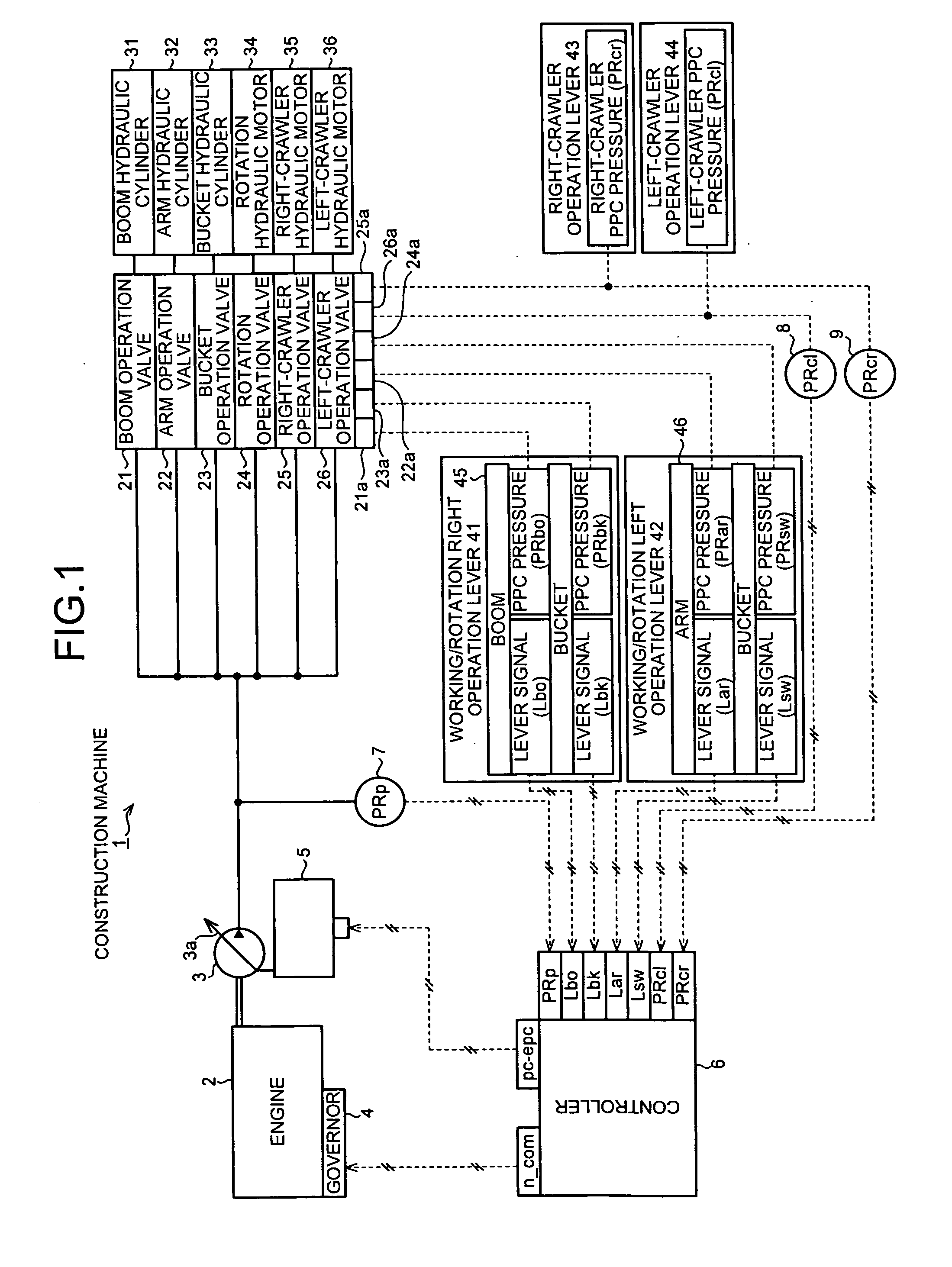
[0163]The first example is based on the configuration example shown in FIG. 1. FIG. 4 and FIG. 6 are control block diagrams showing a processing content performed in the controller 6.

[0164]As shown in FIG. 4, the target flow rate Qbo of the corresponding boom hydraulic cylinder 31, the target flow rate Qar of the arm hydraulic cylinder 32, the target flow rate Qbk of the bucket hydraulic cylinder 33, the target flow rate Qsw of the rotation hydraulic motor 34, the target flow rate Qcr of the right-crawler motor 35, and the target flow rate Qcl for every left-crawler motor 36 are respectively calculated in the hydraulic actuator target flow rate calculating unit 50 based on the boom lever signal Lbo, the arm lever signal Lar, the bucket lever signal Lbk, the rotation lever signal Lsw, the right-crawler pilot pressure PRcr, and the left-crawler pilot pressure PRcl.

[0165]The functional relations 51a, 52a, 53a, 54a, 55a, and 56a of the op...

second example

[0232]The second example will now be described.

[0233]The configuration of the construction machine 1 of the second example is based on the configuration example shown in FIG. 3, where the PTO shaft 10, the generator motor 11, the electrical storage device 12, the inverter 13, the rotation sensor 14, and the voltage sensor 15 are added to the configuration example of FIG. 1, and the generator motor 11 performs the electrical motor operation and the power generating operation.

[0234]FIG. 5, FIG. 6, FIG. 7 and FIG. 8 are control block views showing a processing content performed in the controller 6.

[0235]FIG. 5 is a view corresponding to FIG. 4 of the first example, and description on the portions overlapping with FIG. 4 will be omitted.

[0236]As shown in FIG. 5 and FIG. 6, in the second example, when the engine target revolution ncom is selected in the minimum value selecting unit 65 similar to the first example, the process described below is executed with reference to the control bloc...

third example

[0319]In the second example described above, description is made based on the hydraulic rotation system for rotating the upper rotation body of the construction machine 1 by unit of the hydraulic actuator (hydraulic motor), but the second example based on an electrical rotation system of rotating the upper rotation body of the construction machine 1 by unit of an electrical actuator will be described below.

[0320]FIG. 15 is a configuration view of the third example and shows a configuration of the construction machine 1 mounted with the electrical rotation system.

[0321]As shown in FIG. 15, similar to the configuration of FIG. 3, the PTO shaft 10, the generator motor 11, the electrical storage device 12, the inverter 13, the rotation sensor 14, and the voltage sensor 15 are added to the first example of FIG. 1, and the electrical motor operation and the power generating operation are performed by the generator motor 11, but components for rotating the upper rotation body with the elec...


PUM


Abstract

An object of the present invention is to operate the working machine etc. with satisfactory responsiveness as intended by the operator while enhancing engine efficiency, pump efficiency, and the like, where a first engine target revolution ncom1 adapted to a current pump target discharge flow rate Qsum is set, and when determined that the current pump target discharge flow rate Qsum is greater than a predetermined flow rate (10 (L/min)), a revolution nM (e.g., 1400 rpm) greater than an engine low idle revolution nL is set as a second engine target revolution ncom2 determining that operation levers 41 to 44 switched from a non-operation state to an operation state. The engine revolution is controlled so that the second engine target revolution ncom2 is obtained if the second engine target revolution ncom2 is equal to or greater than the first engine target revolution ncom1.

Description

TECHNICAL FIELD[0001]The present invention relates to a control device of an engine, a control device of an engine and a hydraulic pump, and a control device of an engine, a hydraulic pump, and a generator motor, in particular, to a control device that is used when driving the hydraulic pump with the engine.BACKGROUND ART[0002]A diesel engine is mounted on construction machines such as hydraulic shovel, bulldozer, damp truck, wheel loader and the like.[0003]Describing the outline of the configuration of a conventional construction machine 1 using FIG. 1, a hydraulic pump 3 is driven with a diesel engine 2 as a drive source, as shown in FIG. 1. A variable displacement hydraulic pump is used for the hydraulic pump 3, where capacity q (cc / rev) is changed by changing a tilt angle etc. of a swash plate 3a. The pressurized fluid discharged from the hydraulic pump 3 at a discharge pressure PRP and flow rate Q (cc / min) is supplied to each hydraulic actuator 31 to 36 such as boom hydraulic c...

Claims


Application Information

Patent Timeline
IPC IPC(8): F16D31/02H02P9/04
CPCB66F9/22F02D41/021F02D31/001F02D29/04
Inventor MORINAGA, JUNKAWAGUCHI, TADASHIINOUE, HIROAKI
Owner KOMATSU LTD
Why Eureka
Try Eureka