Single-polarization high power fiber lasers and amplifiers

Inactive Publication Date: 2005-10-11
IMRA AMERICA
View PDF13 Cites 85 Cited by
  • Summary
  • Abstract
  • Description
  • Claims
  • Application Information

AI Technical Summary

Benefits of technology

[0039]In fibers of arbitrary diameter, polarization-stable modelocked operation is possible in fiber cavities containing sections of high birefringence fiber. Passive modelocking is enabled by the incorporation of a saturable absorber into the cavity. Modelocking stability is ensured when the life-time of the saturable absorber is smaller than the single-pass group delay between the polarization eigenmodes in each of the fiber sections.
[0040]More generally, in the presence of stray reflections in a passively modelocked laser cavity, pulse stability can be ensured when the time delay between the main pulse and the ‘stray’ pulse generated by the stray reflection is longer than the life-time of the intra-cavity saturable absorber. Specifically, a stable passively modelocked multi-mode fiber laser is constructed when the life-time of the saturable absorber is shorter than the single-pass group delay between the first and the next higher-order mode inside the fiber.
[0041]As an alternative, a high-power fiber laser can be constructed using positive dispersion rare-earth-doped amplifier fiber and a narrow bandpass filter as well as a strongly absorbing saturable absorber. In this condition the formation of pulses inside the oscillator that closely approximate parabolas (in the following, to be referred to as parabolic pulses) can be stable, allowing for a great increase in self-phase modulation inside the oscillator, in turn enabling a great increa

Problems solved by technology

As a result, a large gain is only produced in a

Method used


Image

  • Single-polarization high power fiber lasers and amplifiers
  • Single-polarization high power fiber lasers and amplifiers
  • Single-polarization high power fiber lasers and amplifiers

Examples


Embodiment Construction

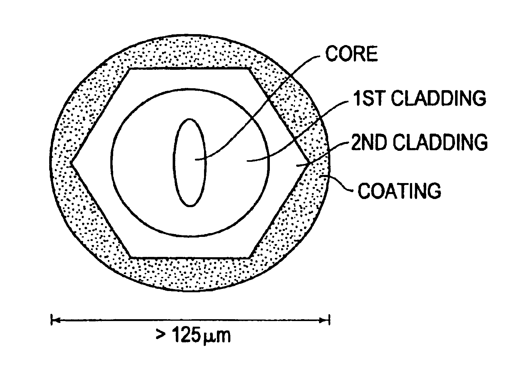
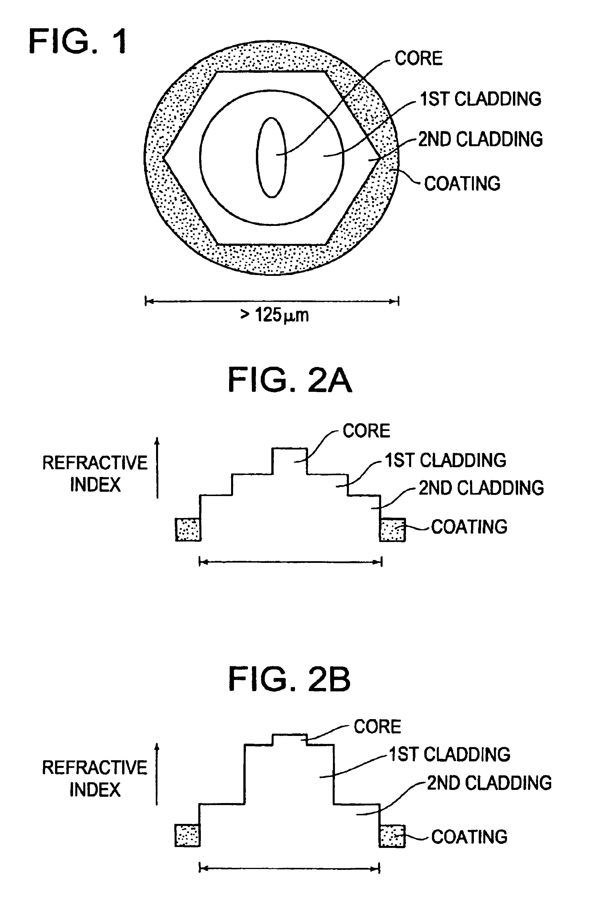
[0066]A schematic drawing of a polarization maintaining large-diameter fiber is shown in FIG. 1. The fiber core has an elliptical shape in order to define the polarization axes of the fiber. The fiber comprises a circular (or non-uniform) inner 1st cladding and a non-uniform (or circular) outside 2nd cladding. Here, the parentheses indicate that the locations of the circular and non-uniform claddings can be reversed. The refractive index of the 2nd cladding is lower than the refractive index of the 1st cladding. In principle any cladding shape can be used for the non-uniform cladding, whether the non-uniform cladding is the 1st or the 2nd cladding. The 1st cladding can consist of germania-doped silica, whereas the 2nd cladding can consist of fluoride glass to obtain a maximum refractive index difference, though any glass compositions with appropriate refractive index differences can be used.

[0067]The fiber can be produced by starting out with a circular perform, which is then machin...


PUM


Abstract

A novel polarization maintaining optical fiber, which can be used as a high-power polarization maintaining fiber laser or amplifier, is described. Insensitivity of the polarization state to external fiber bending and temperature changes is accomplished by minimizing polarization mode-coupling via reducing stresses inside the fiber core via increasing the fiber diameter. Alternatively, polarization mode-coupling can be minimized by an optimization of the fiber coating to minimize stresses at the interface between the fiber and the coating. As a result insensitivity to polarization mode-coupling is obtained at greatly reduced values of birefringence compared to small-diameter fibers. The fiber is of significant use in any application where polarization stability is important, and will be useful in telecommunications applications in particular for reducing polarization mode dispersion. An implementation in a parabolic pulse-producing fiber laser is also described as one specific high power example.

Description

FIELD AND GENERAL DESCRIPTION OF THE INVENTION[0001]The invention relates to single polarization optical fibers, i.e., optical fibers provided with a strong polarization-holding or polarization-maintaining quality; and to fiber lasers formed from rare-earth doped versions of the same.[0002]According to the invention, a novel polarization-maintaining optical fiber is produced by a variety of alternative techniques. According to one embodiment, the fiber is made polarization-insensitive to external bending and temperature change by increasing the fiber diameter to minimize polarization mode coupling through the reduction of stress inside the fiber core. Alternatively, the polarization mode coupling can be reduced by utilizing specific cladding techniques to minimize stresses at the fiber-cladding interface. Stress inducing techniques may be employed within the cladding in order to optimize fiber birefringence.[0003]Rare-earth-doped multi-clad versions of such polarization-maintaining ...

Claims


Application Information

Patent Timeline
IPC IPC(8): H01S3/06H01S3/067H01S3/098G02B6/02G02B6/024G02B6/036G02B6/44H01S3/10
CPCH01S3/06708H01S3/06712H01S3/06729H01S3/094019H01S3/1118
Inventor FERMANN, MARTINHARTER, DONALD J.
Owner IMRA AMERICA
Why Eureka
Try Eureka