Flushing arrangement for WC, and method of operating such flushing arrangement

A flushing device and a technology for flushing water tanks, which are applied to flushing equipment with water tanks, water supply devices, and indoor sanitary plumbing installations, etc., which can solve the problems of reduced acceleration of jet nozzles, and achieve the effects of small deflection, stable pulses, and small turbulence

Inactive Publication Date: 2015-01-21
GEBERIT INT AG
View PDF8 Cites 0 Cited by
  • Summary
  • Abstract
  • Description
  • Claims
  • Application Information

AI Technical Summary

Problems solved by technology

Introducing the aforementioned mixture also produces additional noise
[0004] Tests show that jet nozzle acceleration is greatly reduced when solids are present in the U-bend

Method used


Image

  • Flushing arrangement for WC, and method of operating such flushing arrangement
  • Flushing arrangement for WC, and method of operating such flushing arrangement
  • Flushing arrangement for WC, and method of operating such flushing arrangement

Examples


Embodiment Construction

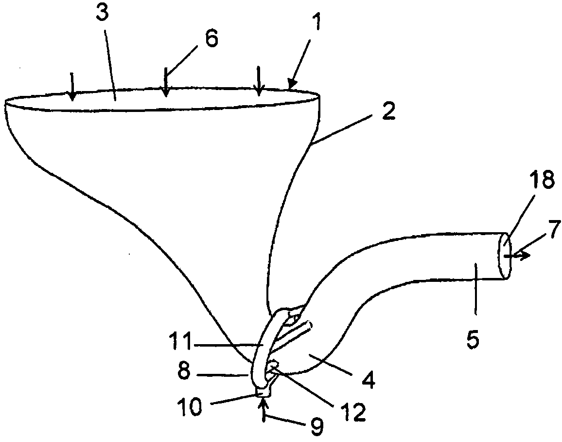
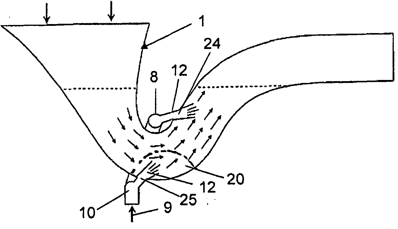
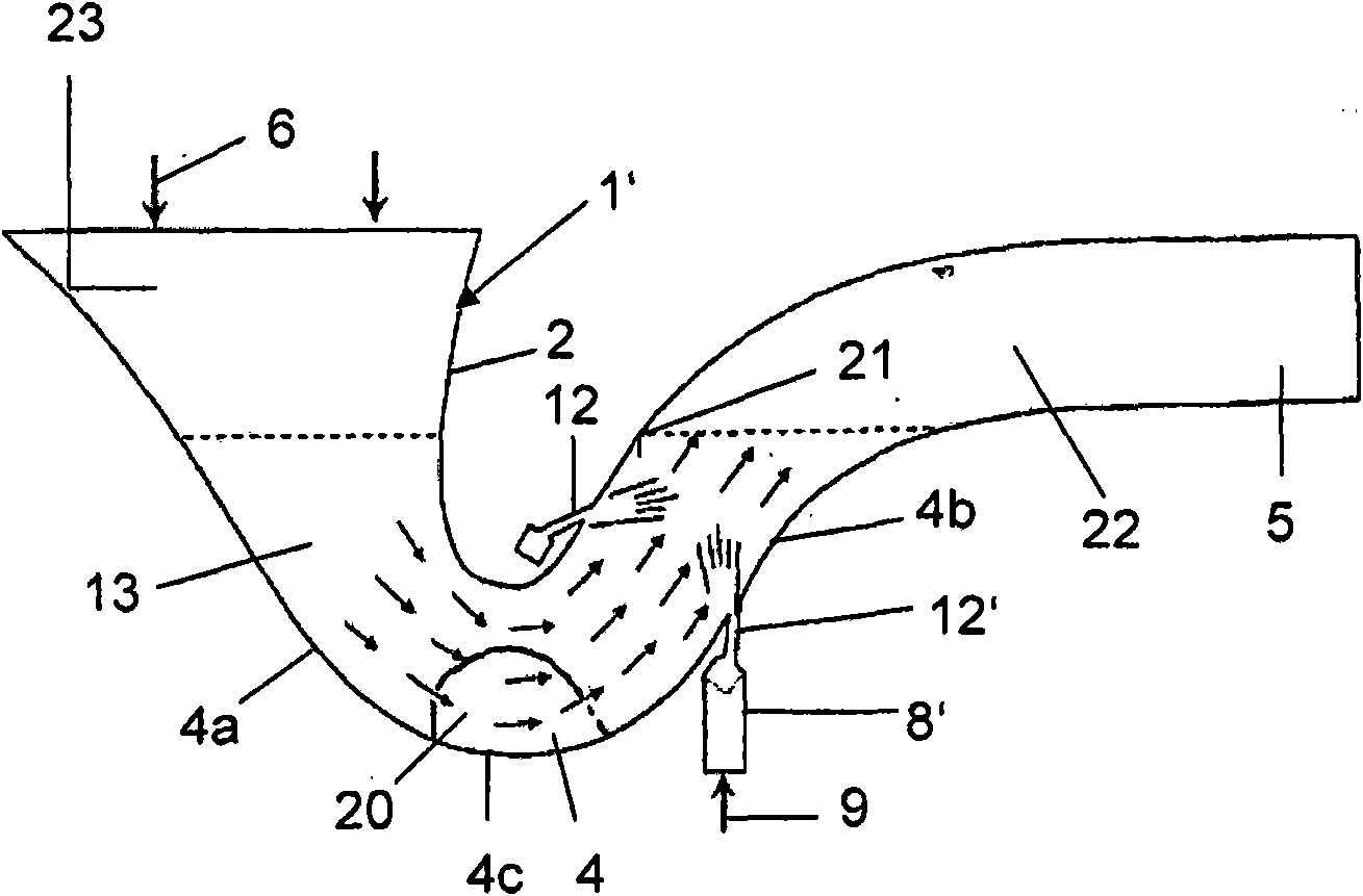
[0023] figure 1 and 2 The flushing device 1 shown in has a WC toilet 2 , for example made of ceramic material, with an inlet 3 and an outlet 18 . The inlet 3 and the outlet 18 have arranged between them a U-shaped bend 4 in which water 13 is stored so as to form an air trap. An outlet 18 is arranged at the end of a waste pipe 5 which is connected to a treatment line in the usual manner. During rinsing, water is supplied in the direction of arrow 6 as is the case in a normal rinsing channel (not shown here). Furthermore, the water 13 present in the U-bend 4 is accelerated by the pulse nozzle arrangement 8 . The pulse nozzle arrangement 8 serves to generate a plurality of flow cones 15 in the water 13 , which are directed towards the outlet 18 . Via the flow cone 15 , the water present downstream of the pulse nozzle arrangement 8 is pushed towards the interior 22 of the waste pipe 5 , thus upwards towards the outlet 18 . Thus, the remainder of the water 13 present in the U-...


PUM


Abstract

#CMT# # / CMT# The device (1) has a toilet bowl (2), which comprises an inlet (3), an outlet (21) and pulse nozzles (8) provided between the inlet and the outlet to generate a pulse. Water (13) in a waste trap bend (4) forms a stench trap and is accelerated for a flushing operation in a direction of the outlet. The pulse nozzles are arranged in a downward region of the toilet bowl and produce a flow cone (14) during flushing, where the flow cone is downwardly directed. The pulse nozzles are arranged at a region of a waste trap water line (24) of the toilet bowl. #CMT# : # / CMT# An independent claim is also included for a method for operating a flushing device. #CMT#USE : # / CMT# Flushing device for a toilet. #CMT#ADVANTAGE : # / CMT# The pulse nozzles are arranged in the downward region of the toilet bowl and produces the flow cone during flushing, where the flow cone is downwardly directed, thus resulting in effective removal of solid objects, and hence enabling effective cleaning and flushing of a waste trap. #CMT#DESCRIPTION OF DRAWINGS : # / CMT# The drawing shows a schematic sectional view of a flushing arrangement. 1 : Flushing device 2 : Toilet bowl 3 : Inlet 4 : Waste trap bend 8 : Pulse nozzles 13 : Water 14 : Flow cone 21 : Outlet 24 : Waste trap water line.

Description

technical field [0001] The invention relates to a flushing device for a WC having a toilet bowl with an inlet and an outlet and between them in a U-shaped elbow a device for generating pulses, through which there is a U-shaped Water in the elbow and forming an air trap can be accelerated in the direction of the outlet for flushing operations. Background technique [0002] The consumption of flushing water in the WC can be significantly reduced when according to the applicant's WO 95 / 04196 a movement is provided during the flushing of the water present in the U-bend by so-called jet nozzles. Water discharged into the U-bend by the nozzle at a relatively high velocity can accelerate the water in the U-bend, in which case the flushing of the U-bend has a better effect. A disadvantage is that the water introduced into the U-bend produces additional noise and the effect of the jet nozzle may at least be greatly reduced by solid matter in the U-bend. [0003] EP-A-1034338 disclo...

Claims


Application Information

Patent Timeline
Patent Type & Authority Patents(China)
IPC IPC(8): E03D11/02E03D11/18E03C1/284E03D1/012E03D3/10
CPCE03D11/08E03D2201/30
Inventor U·英格林A·厄恩格尔根
Owner GEBERIT INT AG
Why Eureka
Try Eureka