
Phase Difference Film, Polarizing Plate And Liquid Crystal Display Device

A retardation film and polarizer technology, applied in polarizing components, instruments, optics, etc., can solve problems such as increased production costs, damage to the quality of polarizers, and reduced productivity

Inactive Publication Date: 2017-10-20
KONICA MINOLTA INC
View PDF43 Cites 0 Cited by
  • Summary
  • Abstract
  • Description
  • Claims
  • Application Information

AI Technical Summary

Problems solved by technology

[0004] Among them, when the above-mentioned low moisture permeability film (film made of PET or acrylic resin) is used as the T1 film, in the melt casting film forming method, in order to heat the ultraviolet absorber, etc. Additives are melted, and it is necessary to check the conditions suitable for melting and form a film under these conditions. Therefore, it is generally not easy to add additives. Therefore, the production cost increases while the productivity of the film is reduced.
In addition, if additives are forcibly added, precipitation (bleeding of additives) will occur, and when the formed film is applied to a polarizer, the quality of the polarizer may be impaired.

Method used

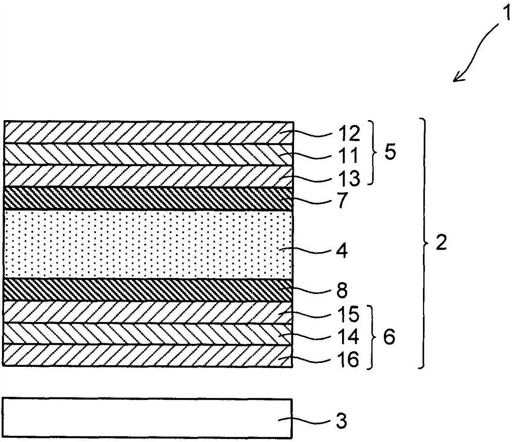
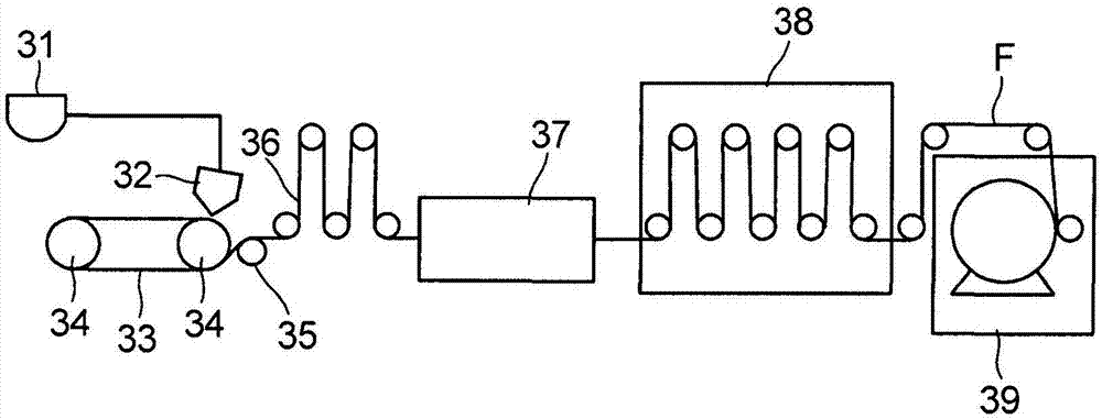

Image

  • Phase Difference Film, Polarizing Plate And Liquid Crystal Display Device
  • Phase Difference Film, Polarizing Plate And Liquid Crystal Display Device
  • Phase Difference Film, Polarizing Plate And Liquid Crystal Display Device

Examples


Synthetic example

[0195]

[0196] Synthesis examples of sugar esters are shown below.

[0197] 【Chemical 14】

[0198]

[0199] Exemplary compound A-1

[0200] Exemplary compound A-2

[0201] Exemplary compound A-3

[0202] Exemplary compound A-4

[0203] Exemplary compound A-5

[0204] 34.2g (0.1 mol) of sucrose, 180.8g (0.8 mol) of benzoic anhydride, and 379.7g (4.8 mol) of pyridine were respectively charged in a four-headed retort with a stirring device, a reflux condenser, a thermometer and a nitrogen inlet tube , the temperature was raised while bubbling nitrogen gas from the nitrogen gas introduction tube with stirring, and the esterification reaction was performed at 70° C. for 5 hours. Next, reduce the pressure in the retort to 4×10 2 Below Pa, after distilling off excess pyridine at 60°C, depressurize the retort to below 1.3×10Pa, raise the temperature to 120°C, and remove most of benzoic anhydride and benzoic acid generated. Next, 1 L of toluene and 300 g of a 0.5...

Embodiment

[0472] The following examples are given to describe the present invention in detail, but the present invention is not limited to these examples. In addition, the expression of "part" or "%" is used in an Example, Unless otherwise specified, it means "part by mass" or "% by mass".

[0473] As nitrogen-containing heterocyclic compounds used in the following examples and comparative examples, the following nitrogen-containing heterocyclic compounds were prepared.

[0474] 【Chemical 27】

[0475]

[0476]

[0477] [Production of Retardation Film A1]

[0478]

[0479] Silica fine particles (Aerosil R972V manufactured by Japan Aerosil Co., Ltd.)

[0480] 11 parts by mass

[0481] 89 parts by mass of ethanol

[0482] The above was stirred and mixed with a dissolver for 50 minutes, and then dispersed with Mantongorin.

[0483]

[0484] The microparticle dispersion 1 was slowly added to the dissolution tank filled with dichloromethane while stirring well. Furthermore, dis...


PUM

PropertyMeasurementUnit
Moisture permeabilityaaaaaaaaaa
Acid valueaaaaaaaaaa
The average particle sizeaaaaaaaaaa

Abstract

The present invention relates to a phase difference film, a polarizing plate and a liquid crystal display device. The phase difference film 13 is the phase difference film of a cellulose ester system of which the delay Ro in an in-plane direction is more than 20 nm, is used as an additive, and contains a first nitrogenous heterocyclic compound having the solubility less than 2% relative to the dichloromethane and a second nitrogenous heterocyclic compound having the solubility more than 15% relative to the dichloromethane.

Description

technical field [0001] The present invention relates to a retardation film, a polarizing plate including the retardation film, and a liquid crystal display device including the polarizing plate. Background technique [0002] In recent years, the glass substrates of liquid crystal cells have become thinner along with the thinning of liquid crystal display devices used as large televisions. If the above-mentioned glass substrate becomes thinner, if the size of the polarizing plate on the visible side relative to the liquid crystal cell changes due to water absorption, there is a concern that the liquid crystal cell will warp and unevenness (color unevenness, brightness unevenness) will occur along with the warping. . Therefore, in the above polarizing plate, the use of a film having lower moisture permeability than conventional cellulose ester-based films (for example, triacetyl cellulose films) has been studied as a protective film located on the visible side with respect to...

Claims


Application Information

Patent Timeline
IPC IPC(8): G02B5/30G02F1/13363G02F1/1335
CPCG02B5/3083G02F1/133528G02F1/13363G02F1/133562G02B1/04G02B5/22
Inventor 別宫启史
Owner KONICA MINOLTA INC
Learn More