Flexible soft physical evidence shooting device and shooting method thereof

A software material evidence and photographic device technology, applied in optics, instruments, photography, etc., can solve the problems affecting the quality of photographic evidence collection, inconvenient use, and the forensic personnel cannot complete the flattening and photography independently, so as to improve the quality of evidence collection and case handling. The effect of improving clarity and improving forensic efficiency

Active Publication Date: 2016-05-18
SHANGHAI CRIMINAL SCI TECH RES INST +1
View PDF6 Cites 0 Cited by
  • Summary
  • Abstract
  • Description
  • Claims
  • Application Information

AI Technical Summary

Problems solved by technology

[0005] 1. The soft object cannot be fixed effectively, making it difficult for forensics personnel to take real images of physical evidence, which affects the quality of photographic evidence collection;
[0006] 2. Forensics personnel cannot complete the work of flattening and taking pictures independently, and need the cooperation of multiple staff members to complete the work, which affects the efficiency of taking pictures;
[0007] 3. There is no dedicated photographic light source on the flattening equipment. After the object is flattened, another staff member is required to light it, so that the forensic personnel can take pictures and collect evidence. It is very inconvenient to use

Method used


Image

  • Flexible soft physical evidence shooting device and shooting method thereof
  • Flexible soft physical evidence shooting device and shooting method thereof
  • Flexible soft physical evidence shooting device and shooting method thereof

Examples


Embodiment Construction

[0053] The specific implementation manners of the present invention will be described in detail below in conjunction with the accompanying drawings of the embodiments.

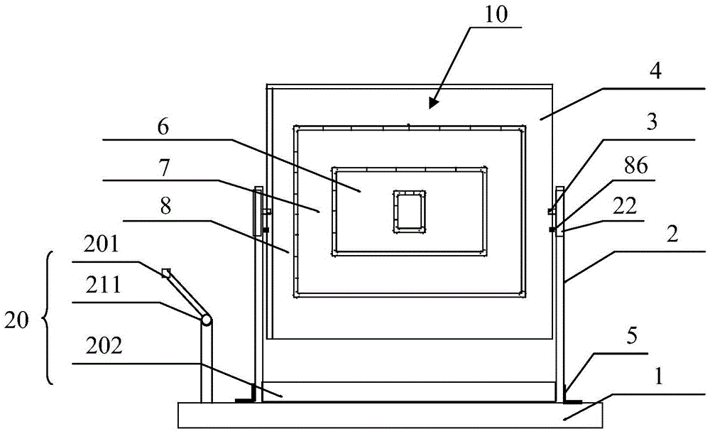
[0054] see figure 1 , the flexible soft evidence photographing device of the present invention includes: a flattening device 10 for flattening the flexible soft evidence, a light source device 20 for developing and illuminating the flattened flexible soft evidence, and a device for imaging and collecting the developed evidence Evidence camera (not shown). The structure of each component will be described in detail below.

[0055] Flattening device 10, see also Figure 1-Figure 2 , which contains:

[0056] The bottom bracket 1 is a plane type frame;

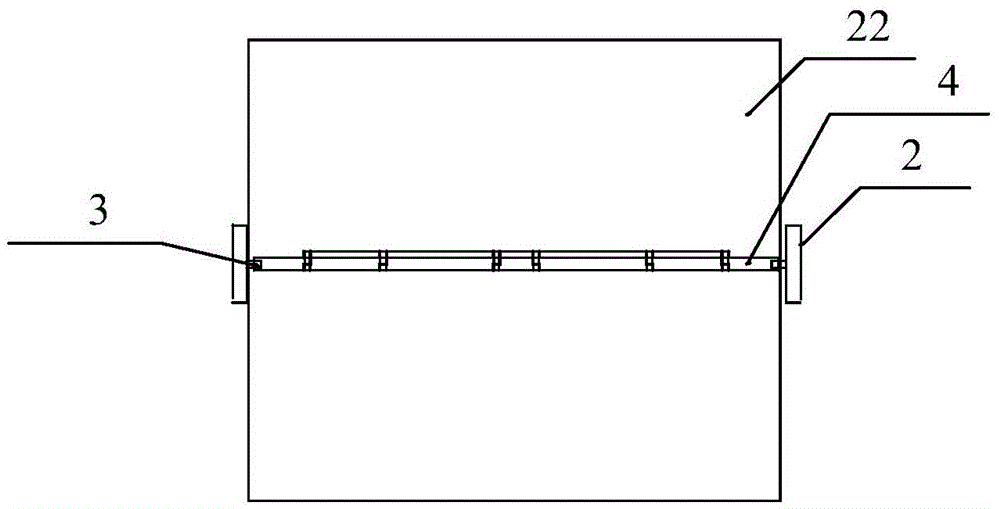
[0057] The fixed bracket 2 is composed of two vertical frames. The two vertical frames are parallel to each other and vertically fixed on the bottom bracket 1. In this embodiment, angle steel 5 is used to vertically fix the bottoms of the two vertical frames o...


PUM


Abstract

The invention discloses a flexible soft physical evidence shooting device and a shooting method thereof, and relates to the physical evidence obtaining technology. The problem of the prior art of inconvenient evidence obtaining can be solved. The flexible soft physical evidence shooting device comprises a flattening device used for flattening a soft physical evidence; a light source device used for the development illumination of the flattened flexible soft physical evidence; and a physical evidence camera used for imaging evidence obtaining of the developed physical evidence. The flattening device comprises a bottom support; a fixing support fixedly disposed on the bottom support; a flattening support, which is disposed on the fixing support, and can be used for rotating and positioning. The flattening support is formed by detachably superposing a plurality of hollow wide edge square frames having different sizes by adopting the magnetic attraction, and a plurality of flattening frames can be formed. The flexible soft physical evidence can be disposed on the corresponding flattening frame according to the size, and the frames, which are smaller than the flexible soft physical evidence can be detached, and the periphery of the flexible soft physical evidence can be disposed between the frame magnetic stone and the inner frame magnetic strip of the flattening support in a clamped manner, and the physical evidence can be flattened by adopting the magnetic force. The form of the flattened flexible object can be fully displayed, and the evidence obtaining efficiency can be improved.

Description

technical field [0001] The invention relates to physical evidence collection technology, in particular to a flexible software physical evidence photographing device and a method thereof. Background technique [0002] Evidence camera is an important equipment for the public security, procuratorate, law, department and other departments to collect evidence for further trace identification. It can provide evidence for solving and finalizing cases, and plays an important role in the trial of criminal and civil cases. [0003] It is difficult for the camera to observe the complete trace image of the potential traces on the flexible soft evidence, especially on the highly wrinkled soft evidence, it is difficult to take a complete trace photo visible to the human eye. To solve this problem, it must be equipped with a physical evidence photo exhibition Flat frame, flatten the wrinkled flexible object first, so that the wrinkled flexible object can be fully flattened to form the best...

Claims


Application Information

Patent Timeline
Patent Type & Authority Applications(China)
IPC IPC(8): G03B15/00G03B15/02
CPCG03B15/00G03B15/02
Inventor 蔡能斌黄晓春邓南崔刘虎金楷淳刘文斌赵雪珺徐宝桢
Owner SHANGHAI CRIMINAL SCI TECH RES INST
Why Eureka
Try Eureka