
Construction management system of smart meter

A management system and smart meter technology, applied in the transmission system, electrical components, etc., can solve problems such as load imbalance, communication efficiency drop, communication breakpoint, etc., achieve low hardware equipment cost and software design cost, and improve deployment flexibility , the effect of reducing complexity

Active Publication Date: 2016-05-18
INSTITUTE FOR INFORMATION INDUSTRY
View PDF6 Cites 1 Cited by
  • Summary
  • Abstract
  • Description
  • Claims
  • Application Information

AI Technical Summary

Problems solved by technology

[0006] However, regardless of the (1) or (2) architecture, the staff must have site survey capabilities or survey tools corresponding to the environment, otherwise it is difficult for the staff to find out the communication quality influencing factors of the deployment environment , if the installation is mandatory, it will avoid multiple communication breakpoints, resulting in a significant drop in overall communication efficiency
Moreover, if the survey tool is not a survey tool dedicated to the survey and deployment environment, the reference of the test results is relatively low, and there will be a considerable difference between the final on-site deployment effect and the expected effect of the on-site survey and its predetermined strategy. drop
[0007] Secondly, the (1) architecture cannot be applied to a more complex deployment environment
When the concentrator and the smart meter are connected by wireless communication, if there is an obstacle between the two, or the location of the concentrator and the smart meter is not good, such as the smart meter is configured in the iron meter box, the smart meter If it is installed deep in the house, the location of the smart meter is too high, or it is blocked by walls, signboards, or other obstacles, it will affect the communication quality between the concentrator and the smart meter, and even cause communication interruption.
In addition, in some countries' systems, it is forbidden to modify the meter, so users or staff cannot set the external interface of the meter antenna to allow barrier-free communication between the smart meter and the concentrator, and the function of wireless communication is equivalent to useless
[0008] In addition, when the concentrator and the smart meter are connected by wired communication (commonly narrow-band power line communication), the slave meter may be centrally installed in the power circuit of the master control device. In addition, it is forbidden to modify the meter. Staff are unable to set up NPL to integrate multiple transformers to adjust the power signal, so it is easy to cause unbalanced load of the power circuit connected to the main control device, which will affect the stability of communication
[0009] Third, in the case of a complex deployment environment and lack of a complete deployment strategy, the deployment and test results of some fields may not be as expected
Deployment personnel can only choose the methods of "installation possible" and "not effective but applicability" for deployment, but it is also prone to the aforementioned communication breakpoints, resulting in a large amount of maintenance work in the future
[0010] Fourth, as far as the (2) structure is concerned, the installation position and space of the bridging device or circuit must be reserved in advance, and the installation must be coordinated with the location and wiring design of each meter, which not only increases the complexity of the circuit configuration, but also increases the complexity of the installation. The method is also limited
Furthermore, the bridging device or circuit must be constructed on site and the construction location is usually adjacent to the location of the electric meter, which may also easily cause troubles for local residents and doubts about why the electric meter circuit should be changed
[0011] It can be seen that the above-mentioned existing smart meter system obviously still has inconvenience and defects in structure and use, and needs to be further improved urgently.
In order to solve the above-mentioned problems, the relevant manufacturers have tried their best to find a solution, but for a long time no suitable design has been developed, and the general product has no suitable structure to solve the above-mentioned problems. This is obviously the relevant industry. Urgent problem

Method used


Image

  • Construction management system of smart meter
  • Construction management system of smart meter
  • Construction management system of smart meter

Examples


Embodiment Construction

[0075] In order to further explain the technical means and effects of the present invention to achieve the intended purpose of the invention, the specific implementation and structure of a smart meter deployment management system proposed according to the present invention will be described below in conjunction with the accompanying drawings and preferred embodiments. , features and their effects are described in detail below.

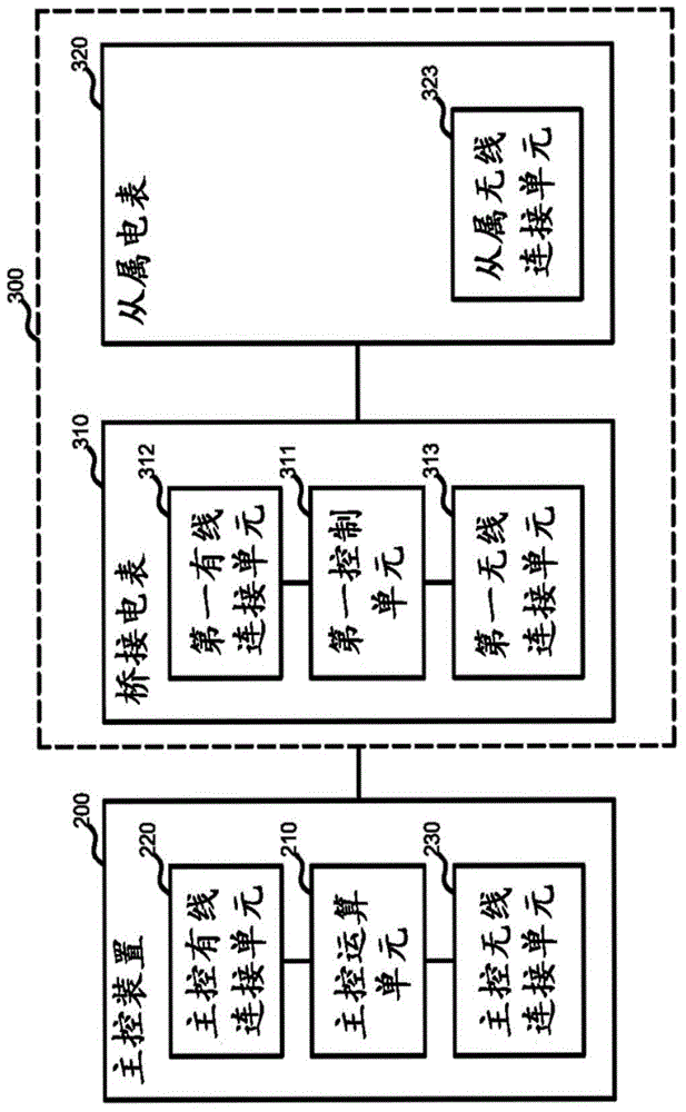
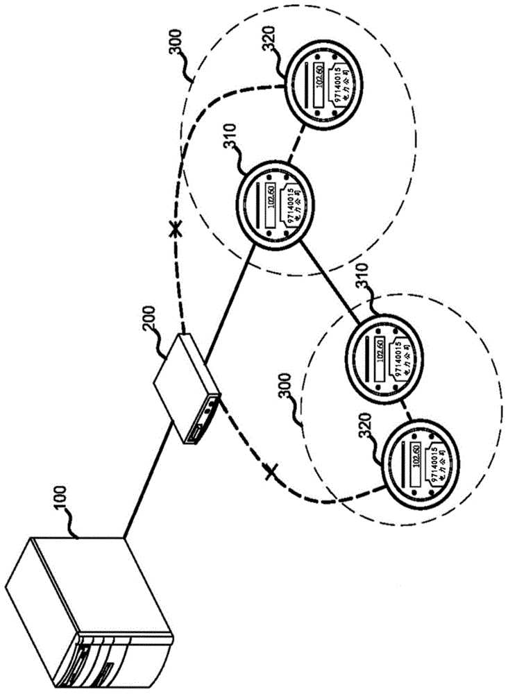
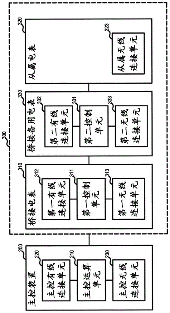
[0076] see Figure 1A A first system architecture diagram showing a smart meter deployment management system according to an embodiment of the present invention, and Figure 1B The first hardware configuration diagram of the smart meter deployment management system according to the embodiment of the present invention is shown. The architecture of this system is: "backend server 100-main control device 200-electric meter group 300". The master control device 200 is the aforementioned concentrator. Here, for the convenience of illustration, the element ...


PUM


Abstract

The invention relates to a construction management system of a smart meter. The construction management system comprises a master control device, a bridging electric meter and an auxiliary electric meter. The master control device is connected with the auxiliary electric meter and the bridging electric meter through wireless communication. When the master control device determines incapability of realizing wireless communication with at least one in the auxiliary electric meter and the bridging electric meter, the bridging electric meter is connected with the master control device through wired communication. The bridging electric meter is connected with the auxiliary electric meter through wireless communication so that the master control device is connected with the auxiliary electric meter through the bridging electric meter.

Description

technical field [0001] The present invention relates to a management system of a smart meter, in particular to a deployment management system of a smart meter which manages the deployment situation of the smart meter and maintains communication. Background technique [0002] Advanced Metering Infrastructure (AMI; also known as smart meter system) is basically composed of smart meters, communication systems, and meter data management systems. The main structures include the following: [0003] (1) The master-slave architecture (Server-Master-Slave) of "backend server-concentrator-smart meter". Among them, the connection between the back-end server (Server) and the concentrator (Concentrator) is through a wide area network (Wide area network, WAN), and the connection method includes mobile communication technology (3G, 3.5G, 4G); physical network line connection ( Such as optical fiber communication); or heterogeneous communication connection technology, for example, the bac...

Claims


Application Information

Patent Timeline
IPC IPC(8): H04L29/08
Inventor 李秉恒林雨洁贺敏慧
Owner INSTITUTE FOR INFORMATION INDUSTRY
Learn More