Precision force applicator for force transducer calibration

A force application device and force sensor technology, applied in the direction of measurement device, force/torque/work measuring instrument calibration/test, instrument, etc., can solve the problem of not being able to produce repeatable results with high precision

Active Publication Date: 2016-05-18
MTS SYSTEMS CORPORATION
View PDF6 Cites 8 Cited by
  • Summary
  • Abstract
  • Description
  • Claims
  • Application Information

AI Technical Summary

Problems solved by technology

Although many methods and devices have been used to apply external load...

Method used


Image

  • Precision force applicator for force transducer calibration
  • Precision force applicator for force transducer calibration
  • Precision force applicator for force transducer calibration

Examples


Embodiment Construction

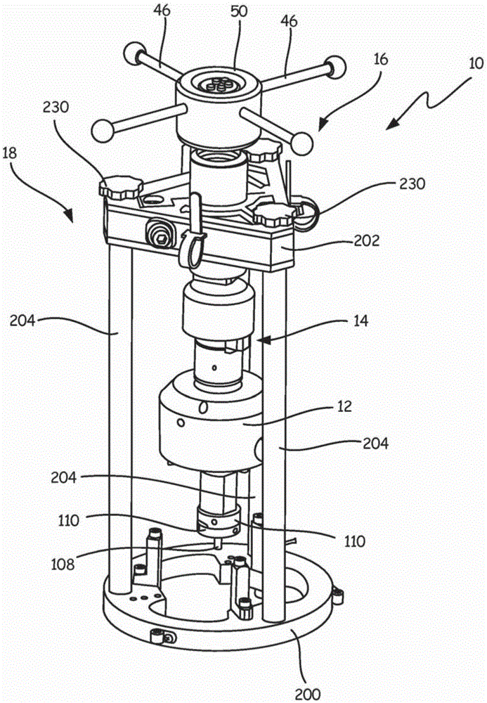
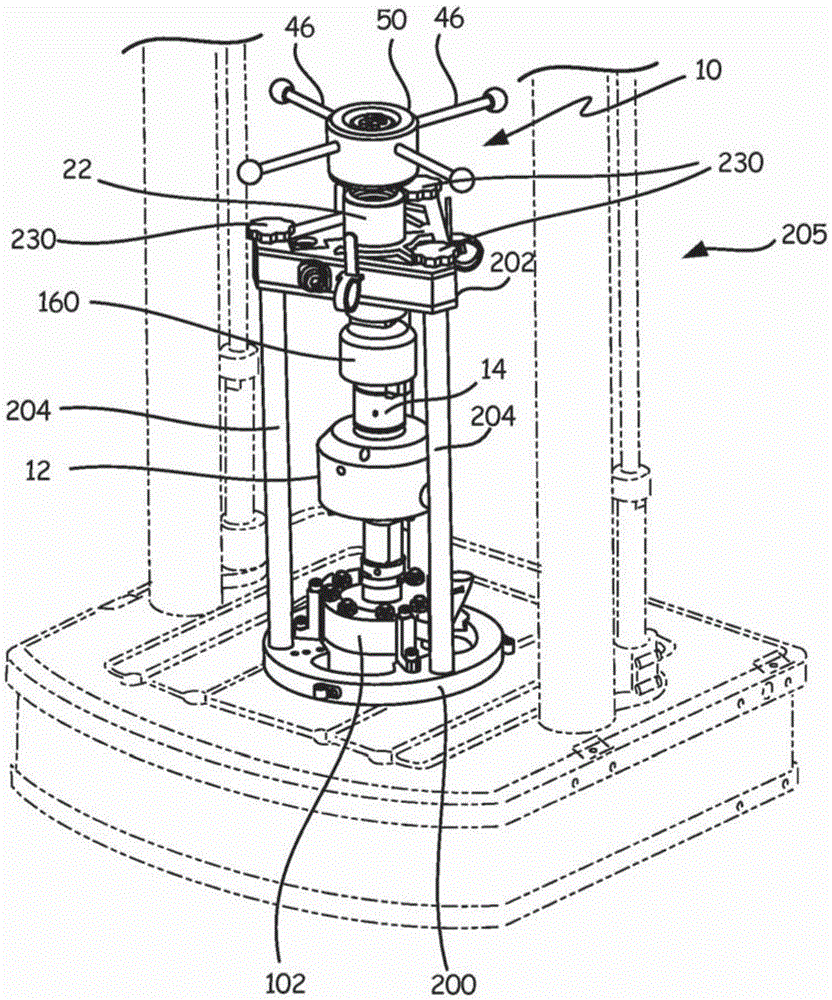
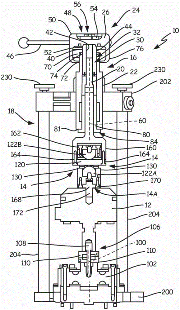
[0028] Aspects of the present invention include, but are not limited to, a precision force applying device assembly, which has a force applying device 10 for generating a precise force on the load sensor 12, which is here as a reference standard; however, The specific types of load sensors described herein do not form any part of the invention. An innovative coupling or coupling assembly 14 is also shown in the figure and can be used to couple force between the force application device 10 and the load cell described below. The force application device 10 includes an actuator 16, which is usually supported to apply a load to the load sensor 12 (and in the image 3 Load sensor under test in 102)

[0029] See image 3 with 6 The actuator 16 includes a moving member 20, which is shown herein as an actuator rod that moves relative to a fixed member 22, which is implemented herein as a support tube. The differential screw assembly 24 couples the moving member 20 to the fixed support o...


PUM


Abstract

A force applicator assembly (10; 10') is disclosed to calibrate an in-situ force transducer (or load cell) (104) in a force (load) applying test machine (125). The force applicator (10) includes stationary member (22; 22') configured to be secured to fixed structure, a moving member (20; 20'), a load cell (12) operably coupled to an end of the moving member (20; 20'); and a differential screw assembly (24; 24') connecting the moving member (20; 20') to the stationary member (22; 22'). A coupling assembly (14) can be used to assure that only tension or compression loads are applied. The coupling assembly (14) can be configured if desired such that no tension or compression loads can be applied. A method to calibrate an in-situ force transducer (104) in a force applying test machine (205) is also provided and uses a force generator (16; 16'; 125) and the coupling assembly (14).

Description

Technical field Background technique [0001] The following discussion is provided as general background information only and is not intended to help determine the scope of the claimed subject matter. [0002] Force measurement sensors require periodic calibration, which is achieved by comparing the sensor under test with a reference standard sensor. Calibration must be performed with incremental force within a certain range of each international standard specification. In many cases, the test machine used to perform the test can be used as a force-applying device for calibration purposes; however, in some cases it is impossible to perform calibration, or the fixture required to perform the calibration introduces unacceptable error. [0003] Under such circumstances, an electrically driven material testing system has the following unique characteristics: its short-term dynamic force capability exceeds its static force. Its dynamic rated force can be maintained for a period of time...

Claims


Application Information

Patent Timeline
IPC IPC(8): G01L25/00G01L27/00
CPCG01L25/00G01L27/002G01N2203/021G01L5/0028F16D1/04
Inventor 布拉德利·D·舒尔茨保罗·M·克鲁格
Owner MTS SYSTEMS CORPORATION
Why Eureka
Try Eureka