Revolving stage with color powder dispensing device

A color powder and stage technology, which is used in stage installations, installations for theaters and circuses, entertainment, etc., can solve problems such as inconvenience of spraying color powder, and achieve good vibration isolation effect.

Active Publication Date: 2018-01-30
YIWU SCI & TECH INST CO LTD OF ZHEJIANG UNIV OF TECH
View PDF15 Cites 0 Cited by
  • Summary
  • Abstract
  • Description
  • Claims
  • Application Information

AI Technical Summary

Problems solved by technology

[0003] The invention provides a rotating stage with adjustable fan blade height and equipped with a color powder dispensing device, which solves the problem of inconvenient spraying of color powder on the existing rotating stage

Method used


Image

  • Revolving stage with color powder dispensing device
  • Revolving stage with color powder dispensing device
  • Revolving stage with color powder dispensing device

Examples


Embodiment 1

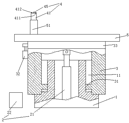
[0039] Embodiment one, see figure 1 , a rotating stage provided with a color powder dispensing device, including a hollow fixed column 1, a lifting structure 2, a hollow lifting column 3 and a table top 5.

[0040] A chute 11 is arranged inside the hollow fixed column 1 .

[0041] The lifting structure 2 includes a lifting cylinder 21 and a hydraulic station 22 for driving the lifting cylinder. The lifting cylinder 21 is arranged inside the hollow fixed column 1 .

[0042] The hollow lifting column 3 is sleeved on the outside of the hollow fixed column 1 . The hollow lifting column 3 is provided with a slide bar 31 . The slide bar 31 is slidably connected in the slide groove 11 . The hollow lifting column 3 is connected with the piston rod of the lifting cylinder 21, that is, driven by the lifting cylinder 21 to lift. The upper end of the hollow lifting column 3 is provided with a slewing bearing 33 . A rotating motor 32 is arranged outside the hollow lifting column 3 . ...

Embodiment 2

[0051] Embodiment two, the difference with embodiment one is:

[0052] see Figure 5 , The table top 5 is provided with 3 installation frames 9 . The platform 5 is connected to the slewing bearing 33 through the mounting feet 9 .

[0053] Specifically: the mounting foot 9 includes a lower section 91 and an upper section 92 . The lower end of the lower section 91 is connected with the slewing bearing 5 . The upper end of the lower section 91 is slidably sleeved on the lower end of the upper section 92 . The lower section 81 is provided with a damping spring 93 supporting the upper section 92 . The upper end of the upper section 92 is provided with a connecting ring 921 . An inner ring 922 passes through the connecting ring 921 . The inner ring 922 is connected with the connecting ring 921 through the rubber ring 7 . The inner ring 922 is pierced with connecting pins 923 . The connecting pin 923 is connected with the lower end of the platform 1 .

[0054] see Figure 6...

Embodiment 3

[0059] Embodiment three, the difference with embodiment two is:

[0060] see Figure 10 , The mounting foot 9 is also provided with a driving mechanism 6 . The inner ring 922 is rotatably connected to the rubber ring 7 , and the rubber ring 7 is fixedly connected with the connecting ring 921 .

[0061] The drive mechanism 6 includes a ratchet 61 , a pawl 62 for driving the ratchet, and a drive lever 63 . The ratchet 61 is coaxially connected with the inner ring 922 . The ratchet 61 is integrated with the inner ring 922 . The pawl 62 is fixedly connected to one end of the driving rod 63 . The upper section 92 is provided with a sliding hole 924 . The other end of the driving rod 63 can slide through the sliding hole 924 two-dimensionally. The lower end of the drive rod 63 is slidably hooked to the lower section 91 along the radial direction of the connecting ring 921 (see Figure 5 ) and connected with the next paragraph. The driving rod 63 is provided with a storage ho...


PUM


Abstract

The invention relates to a revolving stage. A revolving stage provided with a color powder scattering device comprises a stage top, a hollow fixed column, a hollow lifting column arranged at the upper end of the hollow fixed column in a sleeved mode, a lifting structure for driving the hollow lifting column to ascend or descend, a slewing bearing arranged at the upper end of the hollow lifting column and a rotating motor for driving the slewing bearing to rotate, wherein the color powder scattering device is arranged on the stage top and comprises a container and a raising fan, the raising fan comprises a rotary shaft and a plurality of blades, and the container is provided with a feeding port and a raising port. The rotary shaft extends in the vertical direction and is provided with a plurality of rows of threaded holes distributed in the peripheral direction of the rotary shaft, the number of the threaded holes in the same row of threaded holes is at least two, the threaded holes in the same row of threaded holes are distributed in the vertical direction, the blades are provided with threaded connectors and are connected in the threaded holes through threads to be connected with the rotary shaft. The revolving stage has the advantages of being adjustable in blade height and capable of outputting colorful powder, and the problem of inconvenient color powder scattering of an existing revolving stage is solved.

Description

technical field [0001] The invention relates to a revolving stage, in particular to a revolving stage provided with a color powder distribution device. Background technique [0002] The stage is a space platform provided for actors to perform in a theater or on an outdoor venue. It can make the audience's attention focus on the actor's performance and obtain an ideal viewing effect. Some stages can be raised and lowered, while others cannot be raised and lowered. The types of stage include mirror frame stage, stretch stage, arc stage and rotating stage. An existing rotating stage is disclosed in the patent document with the Chinese patent number 2011105767844, the authorized announcement number CN202401794U, and the name "rotary arm symmetrical lifting and rotating stage". The stage in the patent document includes a table top, a hollow fixed The column, the hollow lifting column sleeved on the upper end of the hollow fixed column, the lifting structure driving the hollow l...

Claims


Application Information

Patent Timeline
Patent Type & Authority Patents(China)
IPC IPC(8): A63J5/02E04H3/26
CPCA63J5/025E04H3/26
Inventor 仇翔倪洪杰俞立吴立锋
Owner YIWU SCI & TECH INST CO LTD OF ZHEJIANG UNIV OF TECH
Why Eureka
Try Eureka